Simulate, analyze, and optimize your circuit functionality with the world’s most reliable SPICE simulator. PSpice delivers a complete circuit simulation and verification solution with native analog/mixed-signal analysis.

PSpice includes a comprehensive of tools and analysis engines to allow you quickly and accuratley perform the simulations you need for the task at hand.
Get the gold standard in SPICE simulation for fast simulation times, highest accuracy, and consistent converge you need.

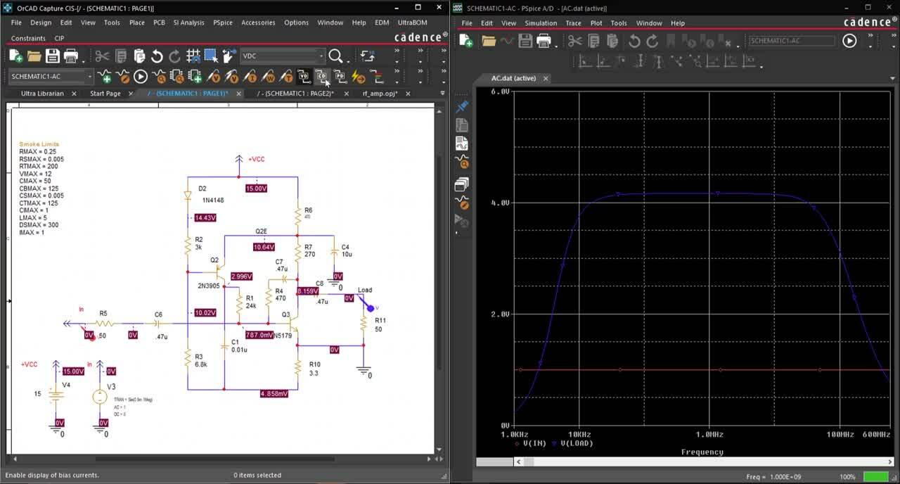
A single environment for both design and simulation streamlines the analysis of critical circuits using native analog and mixed-signal engines directly in the schematic. Only document and model your circuits once- seamless integration between OrCAD Capture and PSpice allows SPICE model assignment and easy-to-understand color-coded simulation results directly in the schematic canvas.
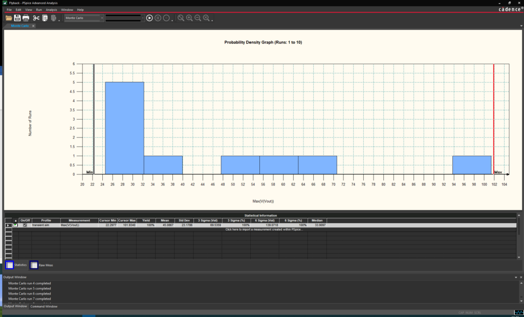
Achieve comprehensive circuit analysis with multiple mixed-signal simulation options in PSpice including time domain (transient), DC sweep, AC sweep, and Bias Point. Advanced analysis enables design optimization with temperature sweeps, sensitivity analysis, Monte Carlo analysis, and more to improve yield, reduce design costs, increase reliability, and fine-tune circuit behavior.
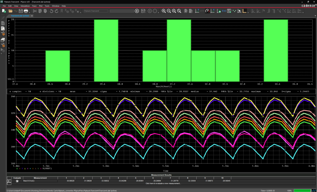
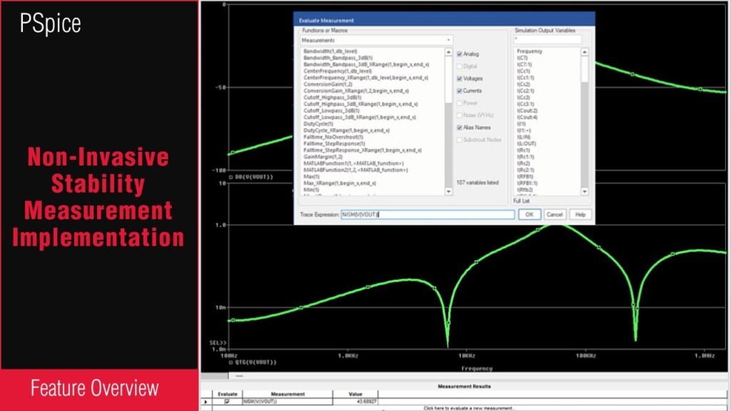
Simulation results are worthless, unless they can be transformed into the analysis you need. With PSpice, it’s easy to visualize circuit behavior with best-in-class waveform viewing and analysis capabilities. Easily transform results to analyze Bode Plots, Fourier transforms, derivatives, and more and automatically calculate numerical measurements using built-in analog and mathematical functions to guarantee proper circuit functionality and performance.
Explore Our Analysis & Reporting Capabilities
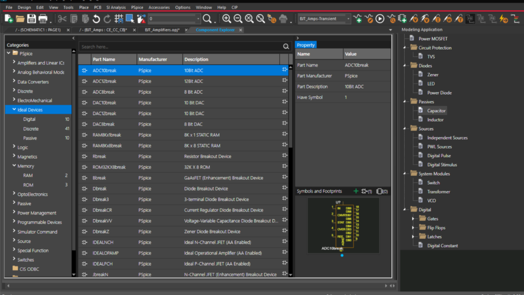
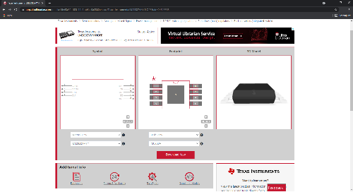
PSpice includes a library of over 33,000 simulation-ready models from various IC vendors for quick definition and simulation of critical circuits. Modeling wizards allow efficient modification of pre-defined models for sources, switches, transformers, capacitors, inductors, and more as well as rapid creation of common components and magnetic parts. Integrated C/C++ and SPICE simulation engines enable you to fully model mixed-signal electronic devices at any level of abstraction directly from the schematic.
Explore Our Library Capabilities
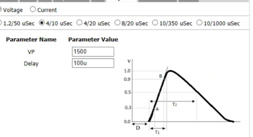
Quickly configure manufacturer’s SPICE models to simulate realistic circuit behavior with the easy, wizard-driven import. The Model Import wizard supports the creation and compiling of Device Model Interface (DMI) models with:
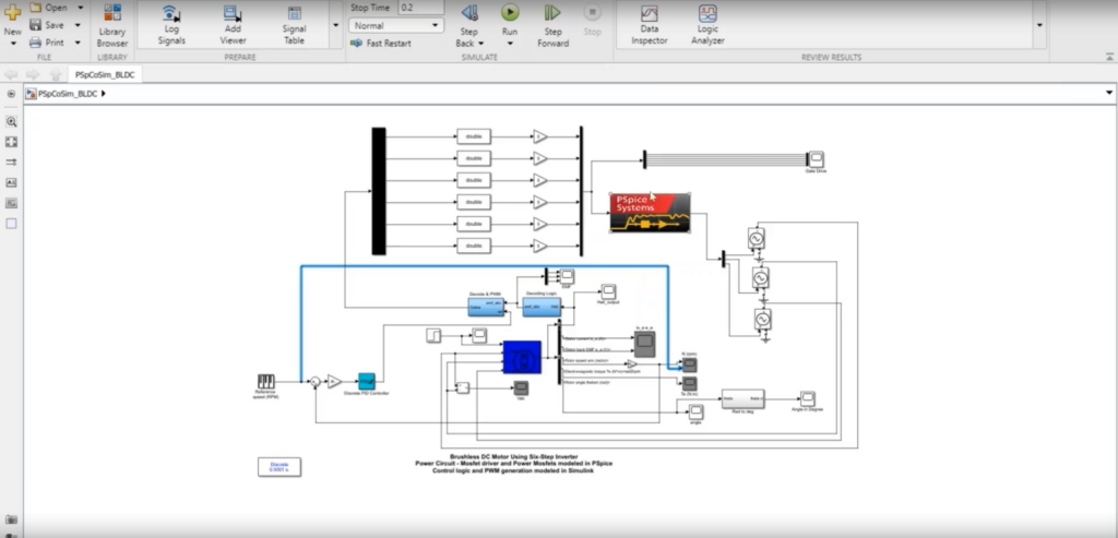
Bi-Directional integration between PSpice and MATLAB Simulink creates a cohesive environment to obtain an accurate full system, electro-mechanical simulation and analysis. Easily combine electrical simulations into system-level analysis, configure customizable settings, and utilize advanced MATLAB plotting capabilities within PSpice to analyze real-life results and debug complete systems virtually.
Device Model Interface (DMI) models enable users to virtually prototype components which are typically difficult to model by defining their behavior with code. DMI models can be used to define the behavior of complex or specialty parts to perform a comprehensive analysis of circuit behavior. PSpice allows you to build and compile DMI models in using System C/C++, Verilog A, and Verilog AMS.
PSpice is used by engineers across the globe building critical products for multiple industries.
PSpice enables automotive engineers to model and predict circuit behavior under various conditions, to identify and resolve of potential issues early in the design process. This leads to more reliable, efficient, and cost-effective automotive electronic systems, which are crucial for the safety and performance of modern vehicles.
Why PSpice for Automotive:
Power Electronics:
Engine Control Units (ECUs):
Infotainment Systems:
Safety and Driver Assistance Systems:
Lighting and Display Systems:
Medical device engineers use PSpice to ensure the design and functionality of their medical devices meet stringent safety and performance standards. PSpice enables the detailed modeling and analysis of complex circuits, allowing engineers to predict and optimize the behavior of medical devices under various conditions. This capability is crucial for developing reliable, efficient, and safe medical equipment, ultimately enhancing patient care and reducing the risk of device failure.
Why PSpice for Medical:
PSpice is used in Medical Device Engineering for Designing:
Engineers in the military or aerospace industry use PSpice to design and validate complex electronic systems that must meet rigorous performance, reliability, and safety standards. This capability is crucial for developing advanced technologies used in critical applications such as avionics, communication systems, and defense electronics, where failure is not an option.
Why PSpice for Mil/Aero:
PSpice is used in Military & Aerospace for Designing:
Engineers designing products in the consumer industry use PSpice to optimize the performance, reliability, and cost-effectiveness of electronic devices. This leads to the development of high-quality consumer electronics, such as smartphones, wearables, and home appliances, that meet market demands for innovation, efficiency, and user satisfaction.
Why PSpice for Consumer Electronics:
PSpice is used in Consumer Electronics for Designing:
For an electrical engineer designing industrial and Industrial Internet of Things (IIoT) products, PSpice is indispensable for ensuring the robustness, efficiency, and reliability of electronic systems deployed in industrial environments. This analysis capability is essential for optimizing the functionality of industrial machinery, sensors, control systems, and communication interfaces, leading to enhanced productivity, reduced downtime, and improved operational efficiency in manufacturing and industrial processes.
Why PSpice for Industrial:
PSpice is used in Industrial electronics and IIoT for Designing:
Engineers designing networking, server, and AI enabled devices use PSpice for optimizing the performance, reliability, and efficiency of their designs. This capability is essential for developing advanced networking equipment, servers, and AI accelerators that require high-speed data processing, low latency, and reliable operation.
Why PSpice for Networking:
PSpice is used in Networking, Servers, and AI for Designing:
Select the solution that best meets your simulation needs. Seamlessly scale up as your requirements change.
Fully Integrated Analysis
The Gold Standard in SPICE
Go Beyond Standard SPICE
Get the latest insights and information
PSpice starts at $2,400/year. Additionally, If you already have an OrCAD PCB design suite then you have access to PSpice basics. You can learn more about pricing here.
Yes! You can get the 30 day free trial which includes access to PSpice as well as the full OrCAD PCB design suite
Yes. Students can join the Cadence academic program and get free access to PSpice and the OrCAD PCB design platform. You can join the Cadence PSpice academic program here
Yes! PSpice has the largest library of models (over 33,000) and modeling tools available to help you access or quickly build the models you need for your simulations.
Yes. You can start with our free walkthrough tutorial and expand through our full PSpice courses (available online and instructor-led). View PSpice course options
PSpice advanced analysis is a unique set of tools and simulation engines available in the PSpice Designer Plus tier which provide additional simulation capabilities to analyze, performance, yield, cost, and overall design reliability. You can learn more about advanced SPICE simulation methods from our eBook.
If you don’t have PSpice yet you can apply for our free trial or student licenses. Then take advantage of our walkthroughs and courses as well as quick how-to videos and guides to get up to speed fast.
PSpice testbench is a unique feature which allows you to run simulations and experiment with your design from with OrCAD Capture without impacting the PCB schematic being developed. This gives you the flexibility you need to analyze and optimize your design while removing the re-work and double data entry that is required from simulation solutions that are decoupled form the PCB design process. Learn more about partial design simulation with PSpice. [link to how-to]
Yes. PSpice supports multiple data export formats including Excel, notepad, csv, txt, PDF, as well multiple mage formats such as TIFF, jpg, png, svg and more. It is very easy to bring your results into other tools for documentation of further analysis and modification.
If you cannot effectively analyze your simulation results the value of simulation is greatly diminished. Probe provides the industry’s best interface to quick and accurately analyze your simulation results. From [need items] Probe provides the tools need to go from simulation to analysis and ultimately action. Learn more here: How to Configure Plot Windows in PSpice | EMA Design Automation (ema-eda.com)