


Shorten your product design cycle with embedded rules, seamless PCB and simulation integration, automated design rule checks, and an integrated component library directly within your schematic canvas.
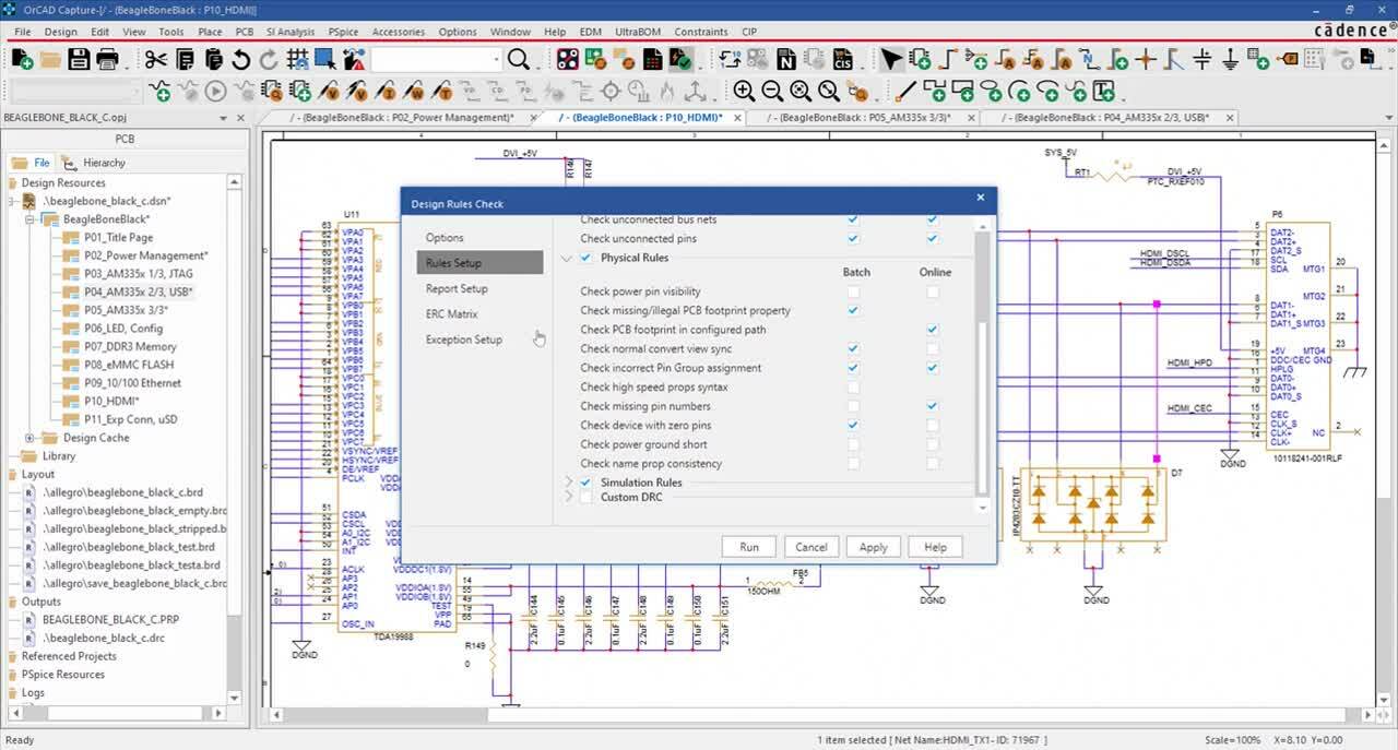
Easily define and embed design rules in the schematic to drive the PCB layout and clearly communicate vital functionality requirements. The customizable ERC Matrix allows for easy definition of errors and warnings when testing connections between pins, hierarchical blocks, and hierarchical ports. Verify schematic accuracy with real-time design rule checks for common electrical, physical, and simulation errors.
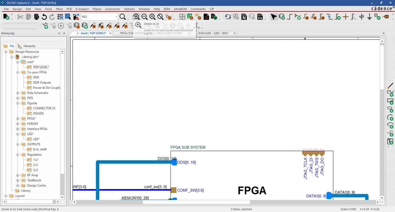
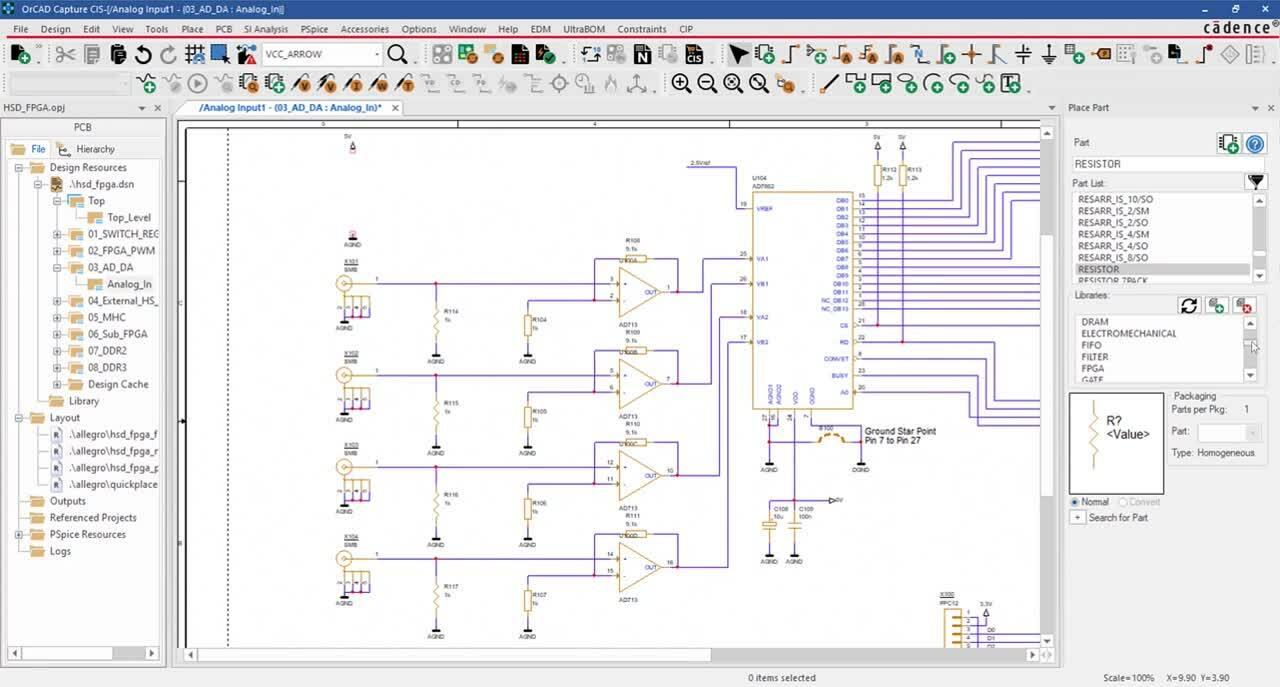
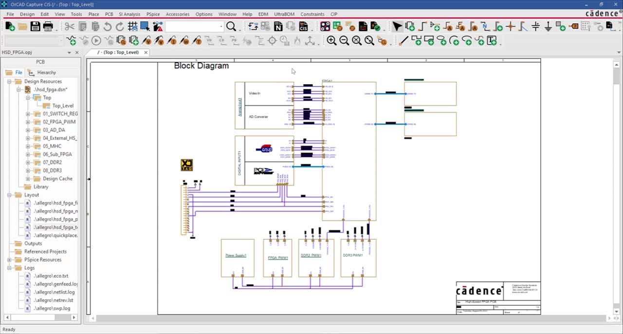
Design efficiently with a standard library of commonly used schematic symbols including power, ground, off-page connectors, no connects, hierarchical blocks, and ports. Easily select parts from an extensive library of commonly used components including discretes, FPGAs, Opamps, Microcontrollers, and more. With integration to Samacsys and Ultra Librarian, easily view live parametric data for millions of components and quickly incorporate verified symbols, footprints, and 3D models into your design. Direct connection to your component database within the schematic canvas guarantees company-approved parts are selected for designs.
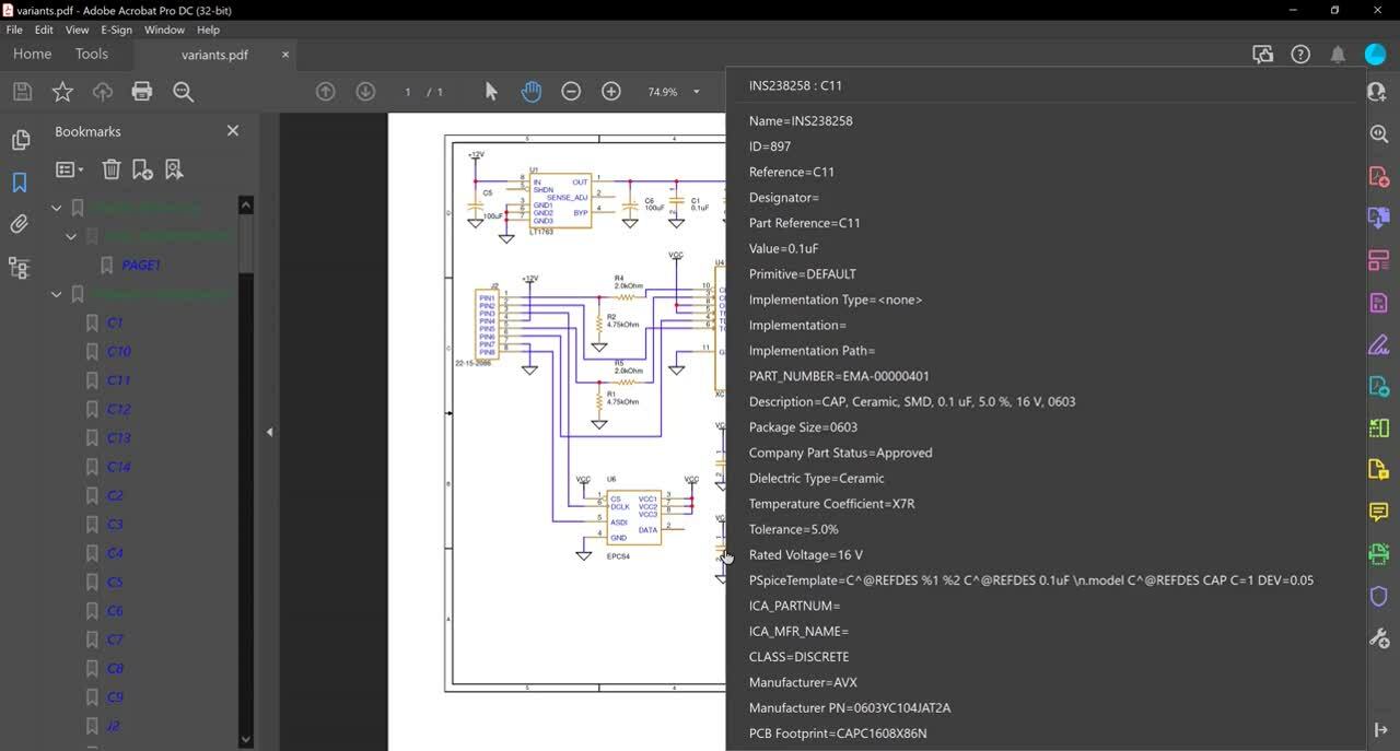
Streamline design reviews with an intelligent PDF of the schematic and interactive identification of components, nets, connectivity, and more. Guarantee component purchasing and assembly with customizable component properties and Bill of Material creation. Accelerate BOM creation with predefined properties, templates, and automatic population of information directly from your component database to create zero-touch BOMs.
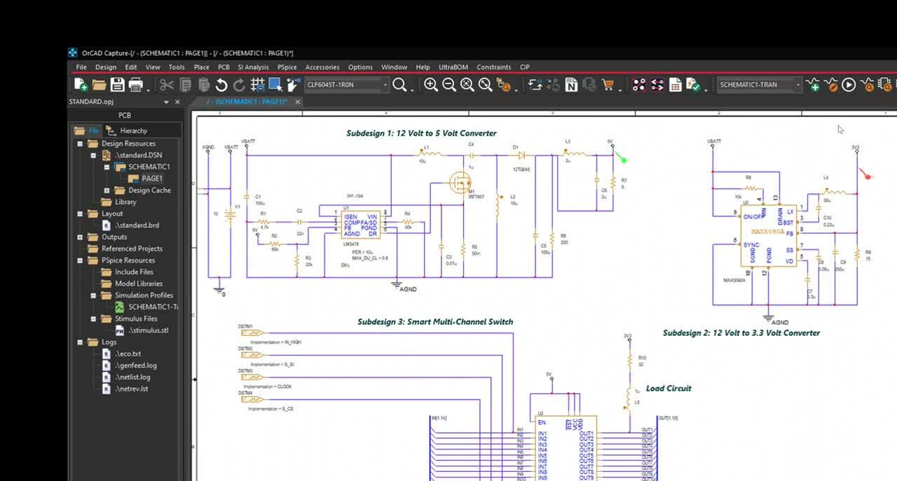
Seamlessly communicate design intent with one-click netlisting and PCB creation. Confidently pass information between the schematic and PCB with bi-directional publishing and automatic identification of changes. Perform early analysis on your critical high speed nets with built in signal integrity analysis. With integrated access to PSpice, easily simulate circuit behavior directly within the schematic; no design translations necessary.
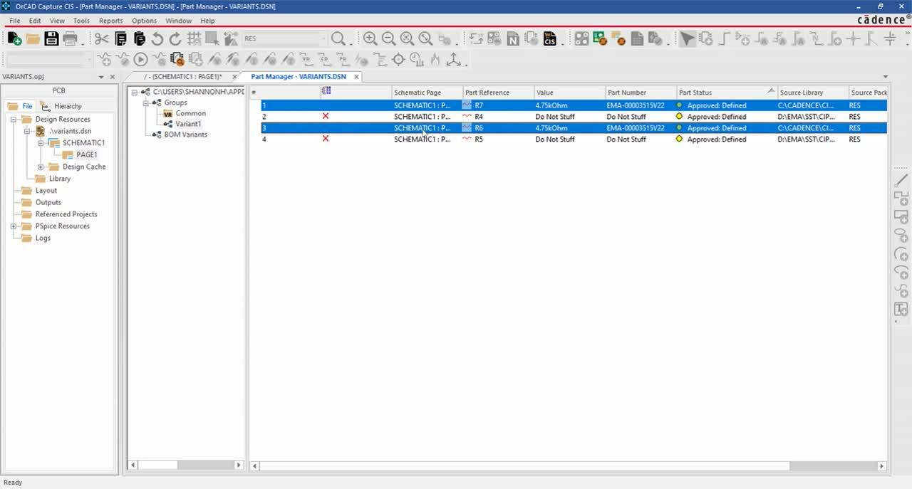
Get the most out of OrCAD Capture with these additional integrations. OrCAD Capture Component Information Portal (CIP) simplifies part management and selection with an easy-to-use interface integrated directly within OrCAD Capture. OrCAD Engineering Data Management (EDM) allows you to manage all aspects of your design data and ensure seamless team collaboration with features such as revision control and library management. Get control over the supply chain with access to critical part information and identify unorderable, obsolete, and high-risk parts directly in the schematic using SE Connect BOM Risk. Constraint Design EE effortlessly manages your high-speed PCB Design rules at the schematic level.