Additional Simulations
This walk-through demonstrates how to setup additional PSpice simulations. After you complete this topic, you will be able to:
- Perform Transient and AC sweep simulations
- View measurements on your simulation plot
- Edit simulation profiles
To follow along, continue working with the design completed in PSpice Walk-through 4 or open the provided board file in the folder directory, PSpice Walk-through 5_Additional Simulations.
If Materials were not downloaded in the beginning of the walk-through, they can be accessed through the Materials tab above for this lesson.
 Open in New Window
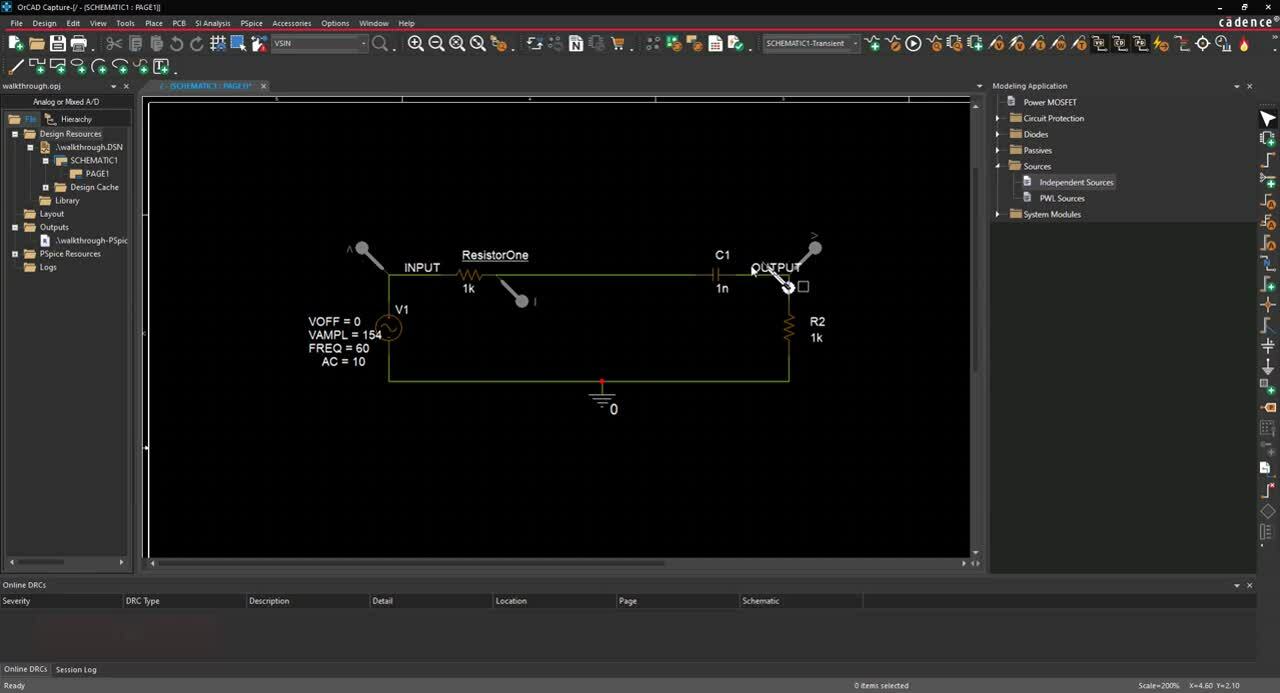
Step 1: Select V1 and press Delete on the keyboard.
Step 2: Select Place> PSpice Component > Modeling Application from the menu.
Step 3: In the Modeling Application, select Sources > Independent Sources.
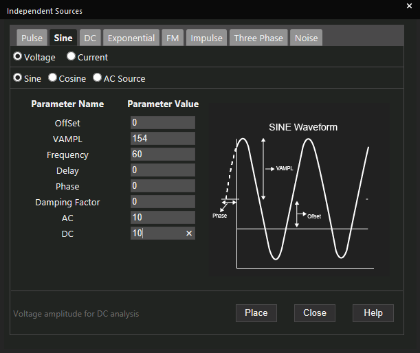
Step 4: Select the Sine tab.
Step 5: Assign AC a value of 10.
Step 6: Assign DC a value of 10.
Step 7: Click Place.
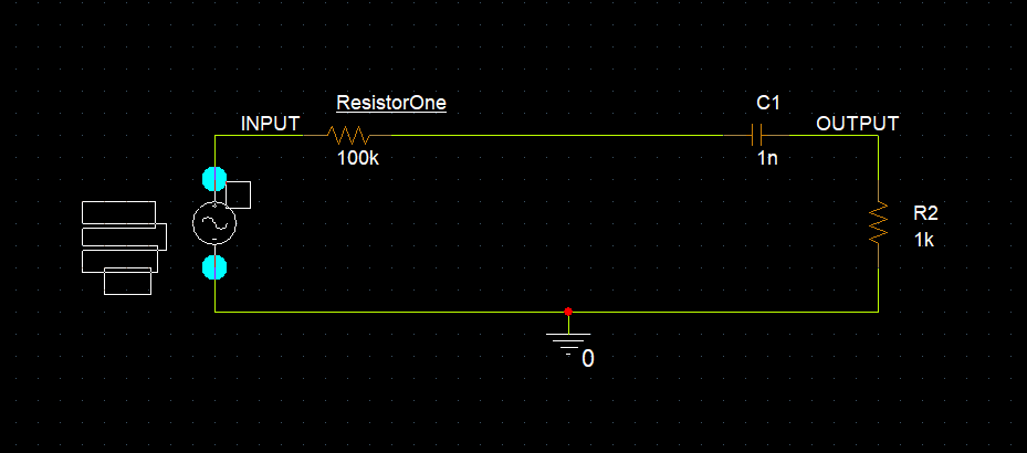
Step 8: Click to place in the circuit.
Step 9: Double click the ResistorOne value of 100k.
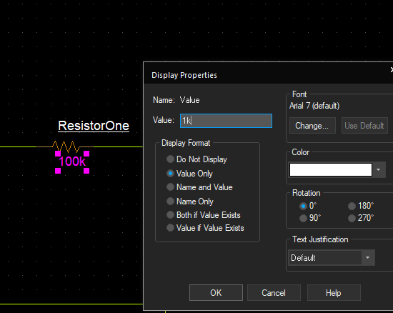
Step 10: Change the value to 1k and click OK.
Step 11: Select PSpice > New Simulation Profile from the menu.
Step 12: Name the new simulation Transient and click Create.
Note: A transient simulation is a measurement of the circuit in the time domain. The results of the simulation are presented as if the circuit is being tested with an oscilloscope. This is the only type of simulation that can be performed on digital designs.
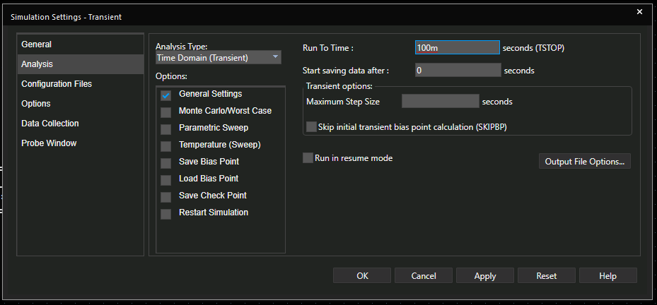
Step 13: Set the Run To Time to 100m. Click OK.
Note: Set maximum step size to determine how many points are measured during the run time. Setting up a maximum step allows you to set a step size that is less than the default.
Step 14: Select the Voltage probe button from the menu or PSpice > Markers> Voltage Level from the menu.
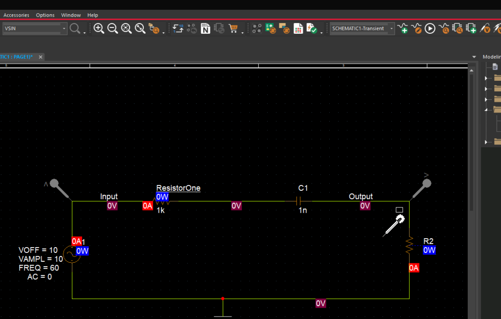
Step 15: Click to place voltage probes at the Input and Output.
Note: To rotate the voltage probe, press R on the keyboard.
Step 16: Right click and select End Mode (ESC).
Step 17: Select the Current probe button from the menu or PSpice > Markers> Current into Pin from the menu.
Step 18: Click to place the current probe on the ResistorOne pin.
Step 19: Right click and select End Mode (ESC).
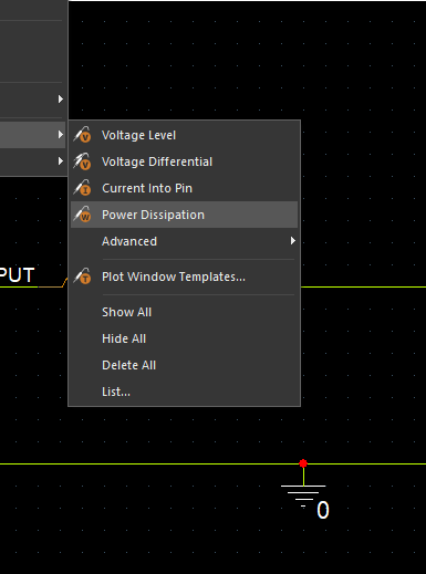
Step 20: Select the Power probe button from the menu or PSpice > Markers> Power Dissipation from the menu.
Step 21: Click to place the power probe on component C1.
Step 22: Right click and select End Mode (ESC).
Note: Voltage probes can be placed on any node, current nodes must be placed on component pins, and power pins must be placed on a component. There are also advanced probes you can select such as Fourier, average, derivative and more.
Step 23: Select PSpice > Run from the menu.
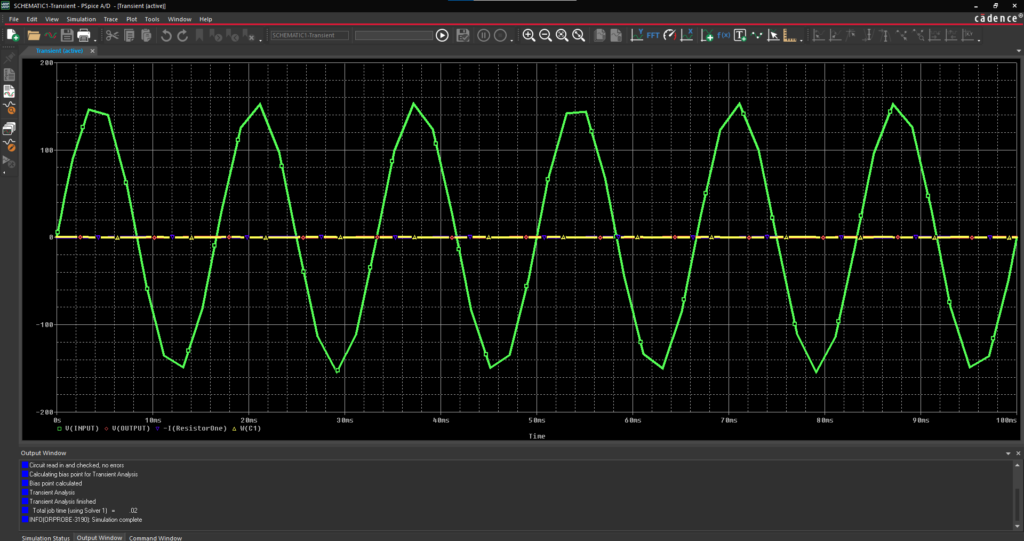
Step 24: View the results in the PSpice A/D window.
Note: Traces are automatically added to the plot based on the probes placed in the schematic.
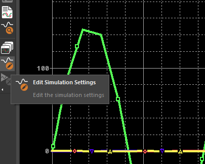
Step 25: In the Plot Window, select the Edit Simulation Settings button.
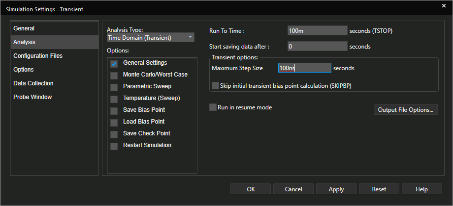
Step 26: Set the Maximum Step Size to 100ns and click OK.
Step 27: Select the Run button on the toolbar or Simulation > Run SCHEMATIC1-Transient from the menu.
Step 28: Select Plot > Add Y Axis.
Note: This allows you to view measurements on the same plot with a different y-axis scale.
Step 29: Right click and select Add Trace.
Step 30: In the Simulation Output Variables, select V(Output). Click OK.
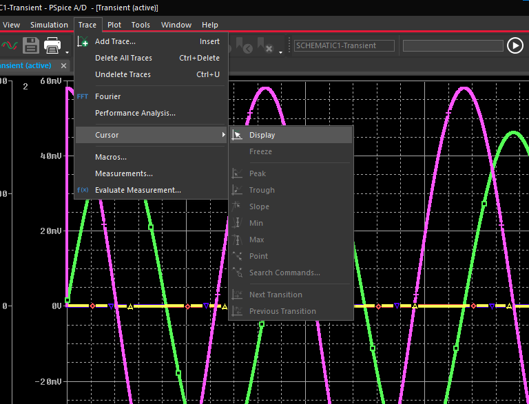
Step 31: Select Trace > Cursor > Display from the menu or use the Toggle Cursor button on the toolbar.
Note: This will show measurements in the plot window such as peak, trough, slope, maximum, minimum or a specific point in the circuit.
Step 32: In the Plot Window, select Edit Simulation Settings.
Step 33: Select Probe Window and show Last Plot.
Note: This will recall the settings of your current plot window, instead of resetting the plot each time a simulation is run.
Step 34: Back in the schematic, select PSpice > New Simulation Profile from the menu.
Step 35: Name the new simulation AC_Sweep and click Create.
Step 36: In Analysis Type, select AC Sweep/Noise.
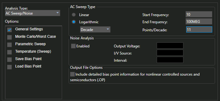
Step 37: Set the Start Frequency to 10.
Step 38: Set the End Frequency to 100MEG.
Step 39: Set Points/Decade to 11. Click OK.
Step 40: Select PSpice > Run from the menu.
Step 41: In the Plot Window, select Trace > Add Trace from the menu.
Step 42: In Simulation Output Variables, select V(output). Click OK.