Lesson 16: SPICE Models
This walk-through will demonstrate how to import and use external SPICE models in OrCAD PSpice Designer. After you complete this topic, you will be able to:
- Download a SPICE model
- Configure the SPICE model file for use in PSpice
- Run the simulation with the SPICE model
To follow along, continue with the design from the previous topic or use the provided materials.
If materials were not downloaded at the beginning of the walk-through, files for this lesson can be accessed through the materials tab above.
 Open in New Window
Creating a Part Library with the Model Editor
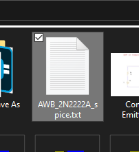
Step 1: Browse to the provided AWB_2N2222A_spice.txt file in File Explorer.
Step 2: Right-click the file and select Copy.
Step 3: Browse to the working directory.
Step 4: Right-click and select Paste. The SPICE model file has been pasted.
Step 5: Right-click the file and select Rename.
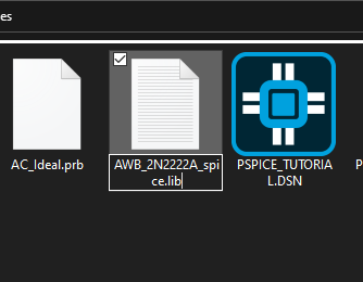
Step 6: Change the extension to .lib and press Enter.
Step 7: You will be prompted that changing the file name extension may make the file unusable. Click Yes to change the extension.
Note: This extension may be in uppercase or lowercase letters for PSpice 23.1. For earlier versions of PSpice, the extension must be written in lowercase letters to be able to run.
Step 8: Open the Start menu and select Cadence PCB Utilities [version] > PSpice Model Editor [version].
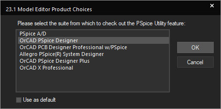
Note: If the Model Editor Product Choices window opens, select OrCAD PSpice Designer and click OK.
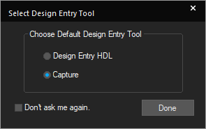
Step 9: Select Capture and click Done in the Select Design Entry Tool window.
Step 10: Select File > Model Import Wizard [Capture] from the menu.
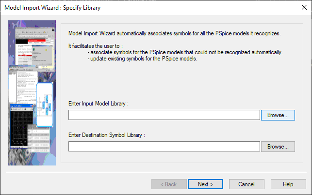
Step 11: The Model Import Wizard opens to the Specify Library page. Select Browse for the Enter Input Model Library field.
Step 12: Browse to the working directory and select the AWB_2N2222A_spice.lib file. Click Open.
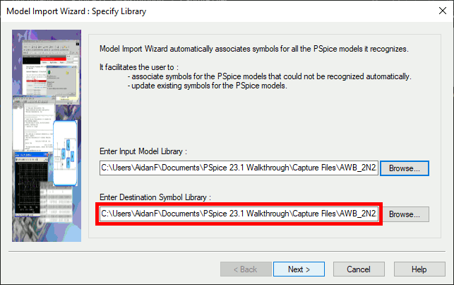
Note: The Destination Symbol Library is populated automatically. This library file will have the same name with a .olb extension.
Step 13: Click Next.
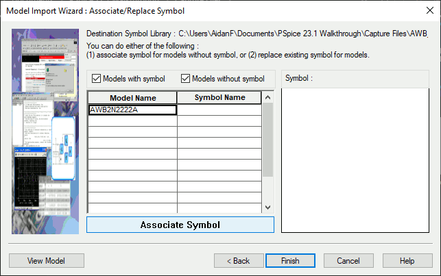
Step 14: The Associate/Replace symbol page opens. If the downloaded part associated with a symbol automatically, it will be shown here. Otherwise, click Associate Symbol.
Note: If no symbol is selected, the schematic symbol will be a rectangular symbol with pins organized in columns.
Step 15: A window opens to select a matching symbol. Select the ellipsis to select a library.
Step 16: Browse to the default Capture library location: C:\Cadence\SPB_[version]\tools\capture\library.
Step 17: Select the Transistor.OLB library and click Open.
Note: This library includes all common transistor symbols.
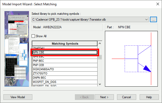
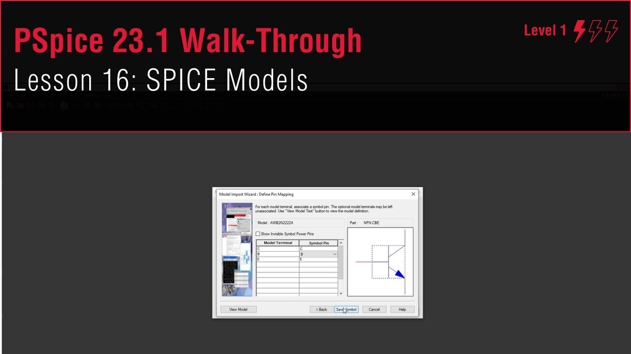
Step 18: Scroll down and select NPN CBE for the symbol. Click Next.
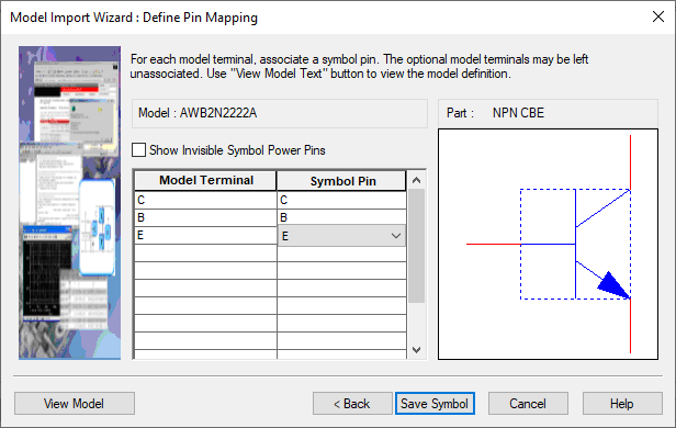
Step 19: A table to define model and symbol pin matching is shown. Match each model terminal with its corresponding symbol pin as shown above.
Step 20: Select Save Symbol and click Finish.
Step 21: A log window appears, listing status messages and any errors that may have occurred during generation. Click OK to close the window.
Step 22: Close the Model Editor.
Adding the Model to the Schematic
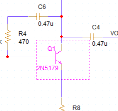
Step 23: Back in the schematic, select transistor Q1 and press Delete on the keyboard.
Step 24: Select Place > Part from the menu to open the Place Part panel.
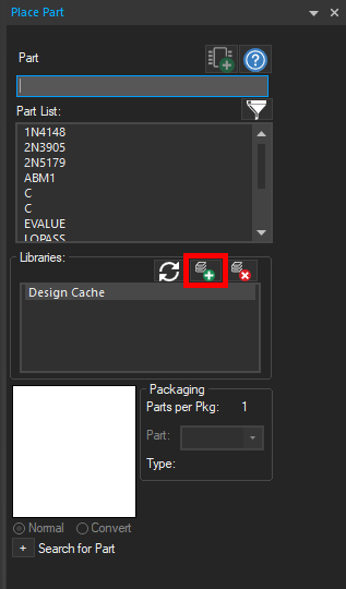
Step 25: Select the Add Library button to add the newly created library.
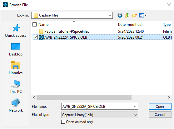
Step 26: The file browser opens. Browse to the working directory and select the AWB_2N2222A_SPICE.OLB file. Click Open.
Note: If you receive an error that the library cannot be placed, close and re-open PSpice Designer.
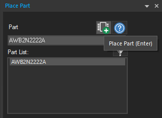
Step 27: The library is added and the part is listed in the Part List. Select the part and click Place Part.
Step 28: Click to place the part in the original location of Q1. Right-click and select End Mode.
Step 29: Double-click the reference designator, U1.
Step 30: Change the reference designator to Q1 and click OK.
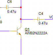
Note: Q1 is underlined, indicating it was changed by the user.
Adding the Library to the Simulation
Step 31: Select PSpice > Edit Simulation Profile from the menu.
Step 32: Select Configuration Files from the panel list on the left.
Step 33: Select Library under Category.
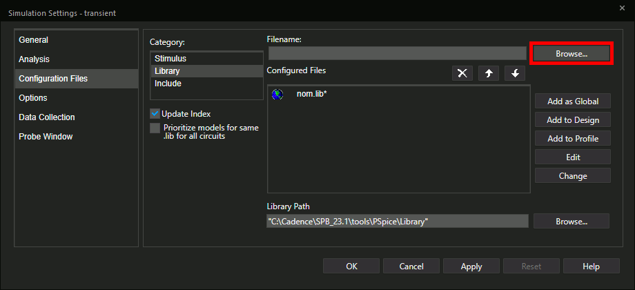
Step 34: Select Browse to search for the SPICE library.
Step 35: Browse to the location of the AWB_2N2222A_spice.lib file, select the file, and click Open.
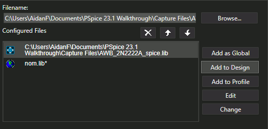
Step 36: Select Add to Design to add the library to the configured libraries list.
Note: Select Add as Global to use the library in any future design.
Step 37: Click OK to save the settings and close the window.
Running the Simulation
Step 38: Select PSpice > Run from the menu to run the simulation.
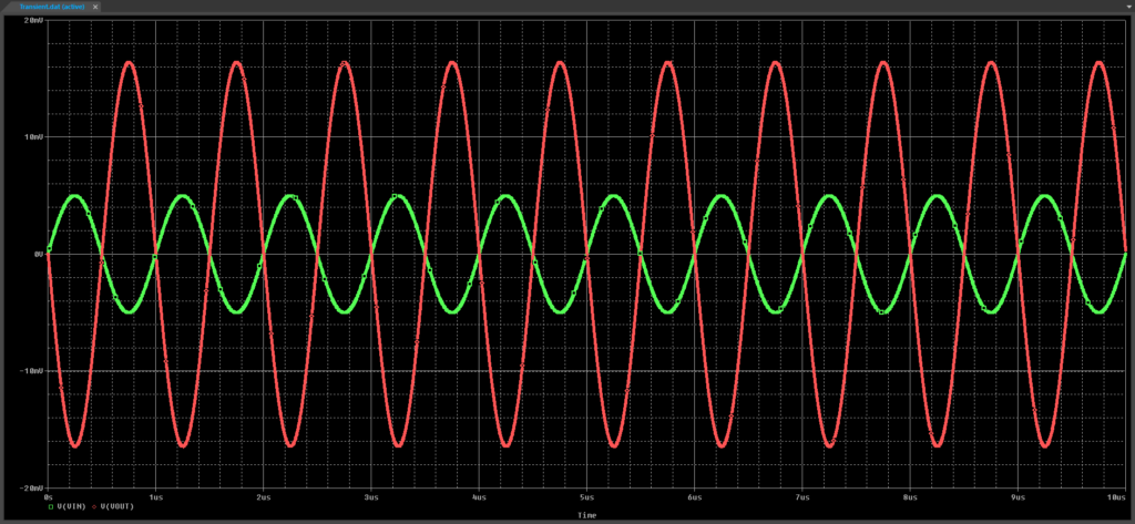
Step 39: View the results. The signal is amplified as it was before.
Step 40: Close the plot window.
Step 41: Select PSpice > Advanced Analysis > Smoke from the menu.
Step 42: In the Product Choices window, select the appropriate license and click OK.
Step 43: Right-click in the table and select Hide Invalid Values.
Note: The derating setting should be the same as it was from the last walk-through.
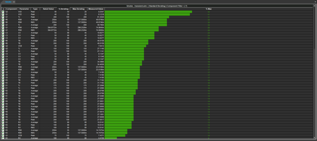
Step 44: View the results. The peak collector-emitter voltage for Q1 is no longer red, indicating that the component is operating within range.
Note: Smoke analysis automatically runs when the Advanced Analysis window is opened. If Q1 still has a red collector-emitter voltage bar, select Run > Start Smoke from the menu.