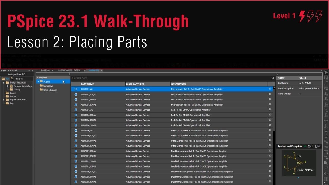
Lesson 2: Placing Parts
This walk-through demonstrates how to place and define PSpice parts into a schematic in OrCAD PSpice Designer. After you complete this topic, you will be able to:
- Place PSpice parts on your schematic
- Perform a part search and place the part
- Rename and edit schematic parts
To follow along, continue with the design from the previous topic or use the provided materials.
If materials were not downloaded at the beginning of the walk-through, files for this lesson can be accessed through the materials tab above.
 Open in New Window
Placing Generic PSpice Parts
Note: To automatically annotate reference designators during component placement, select Options > Preferences from the menu. Select the Miscellaneous tab and check the option for Automatically Reference Placed Parts. Click OK to save the settings.
Step 1: Select Place > PSpice Part > Source > Voltage Sources > DC from the menu.
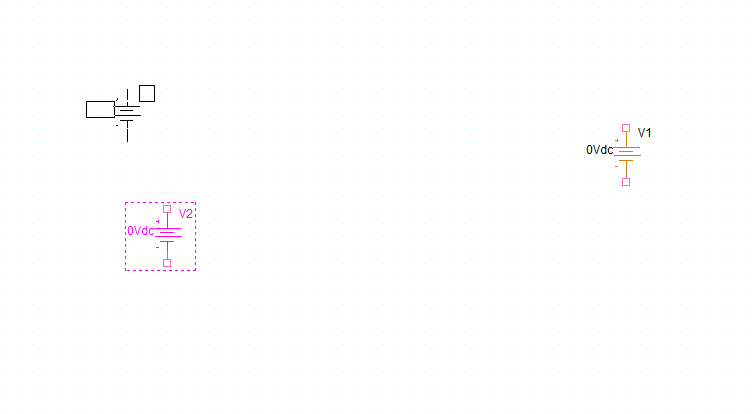
Step 2: Click to place the sources in the schematic. Right-click and select End Mode when finished.
Step 3: Select Place > PSpice Part > Resistor from the menu.
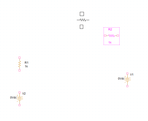
Step 4: Click to place the resistors in the schematic. Right-click and select End Mode when finished.
Note: To rotate a component, press R on the keyboard.
Step 5: Select Place > PSpice Part > PSpice Ground from the menu.
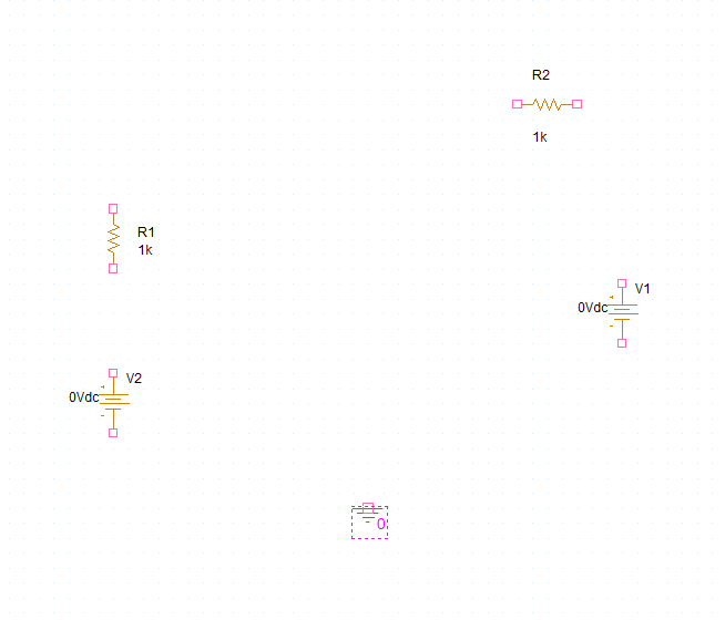
Step 6: Click to place the ground in the schematic. Right-click and select End Mode when finished.
Note: Make sure to place a PSpice Ground symbol. PSpice ground with a net name of 0 is required for the simulation to run properly.
Searching for PSpice Parts
Step 7: Select Place > Component from the menu to open the Unified CIS tab.
Step 8: Select the PSpice category from the Categories list.
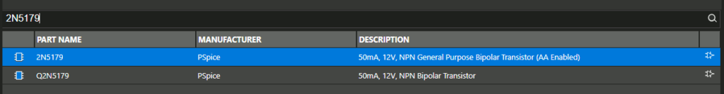
Step 9: Enter 2N5179 into the search field. Press Enter to search.
Note: This will return all parts with 2N5179 in the name. Parts can also be searched by keyword or description.
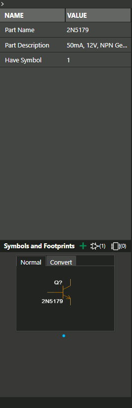
Step 10: Select the part with name 2N5179. Additional part information including the symbol will be shown in the column on the right.
Step 11: Double-click the listing or right-click and select Place to attach the part to your cursor.
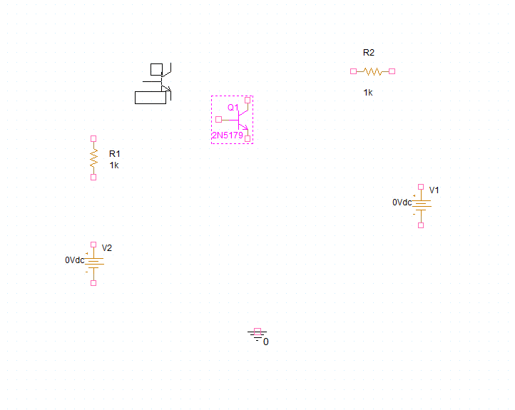
Step 12: Click to place the part in the schematic. Right-click and select End Mode.
Note: Components can be adjusted by clicking and dragging.
Defining Component Values
Step 13: Double-click the value for V2 (0Vdc) to change it.
Step 14: Enter 5V and click OK.
Step 15: Double-click the value for V1. Enter 10V and click OK.
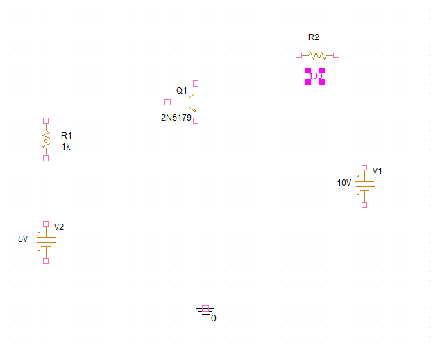
Step 16: Double-click the value for R2. Enter 100 and click OK.
Note: SI prefixes can be added to component values. These are not case-sensitive, so m will be interpreted as “milli-” regardless of whether it is uppercase or lowercase. For the prefix “mega-,” use the keyword “MEG.”