Lesson 4: Bias Point Simulation
This walk-through will show how to set up a PSpice simulation. After you complete this topic, you will be able to:
- Configure a bias point simulation
- Run the simulation and analyze results
- View voltage, current, and power results directly on the schematic
To follow along, continue with the design from the previous topic or use the provided materials.
If materials were not downloaded at the beginning of the walk-through, files for this lesson can be accessed through the materials tab above.
 Open in New Window
Configuring a Bias Point Simulation
Step 1: Select PSpice > New Simulation Profile from the menu.
Step 2: Name the simulation profile Bias_Point and click Create.
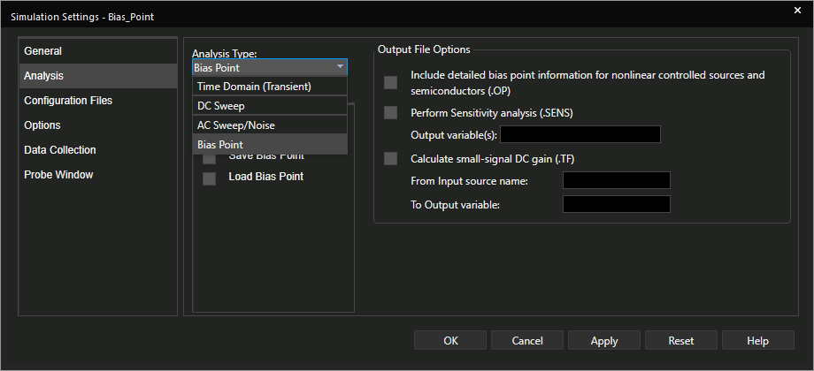
Step 3: Select Bias Point from the Analysis Type drop-down menu.
Step 4: Leave the settings as the defaults and click OK.
Running a Bias Point Simulation
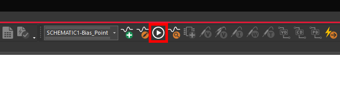
Step 5: Select PSpice > Run from the menu or the Run button on the toolbar to start the simulation.
Step 6: The PSpice A/D window will open but not show a plot. Close the window.
Note: A bias point simulation will not show anything in the plot window.
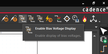
Step 7: Select the Enable Bias Voltage Display button from the toolbar.
Note: This can also be activated by selecting PSpice > Bias Points > Enable Bias Voltage Display.
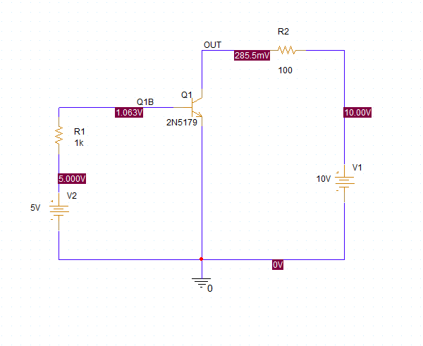
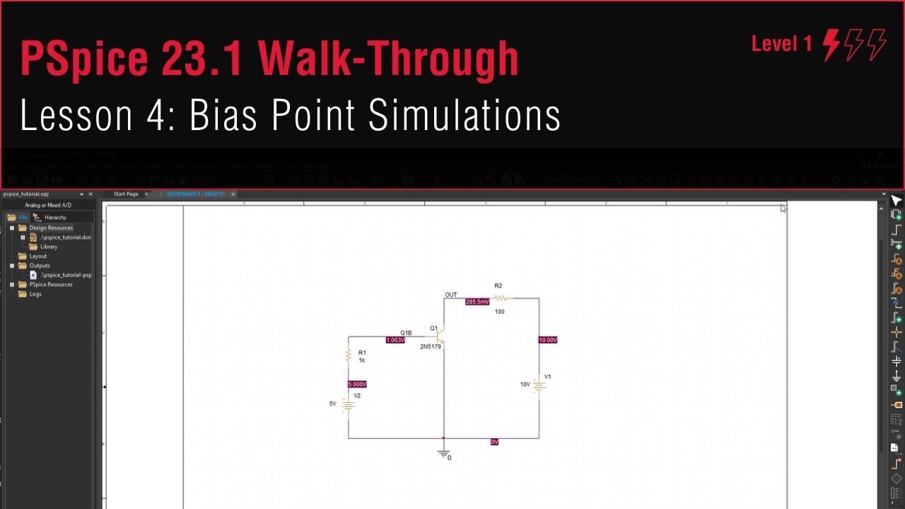
Step 8: View the bias point result voltages at each net in the schematic.
Step 9: Select the Enable Bias Voltage Display button to toggle the voltage display off.
Step 10: Select Enable Bias Current Display button from the toolbar.
Note: This can also be activated by selecting PSpice > Bias Points > Enable Bias Current Display.
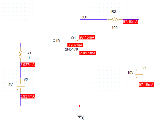
Step 11: View the bias point result currents for each component.
Note: Current bias point values are displayed on the component pins.
Step 12: Select the Enable Bias Current Display button to toggle the current display off.
Step 13: Select Enable Bias Power Display button from the toolbar.
Note: This can also be activated by selecting PSpice > Bias Points > Enable Bias Power Display.
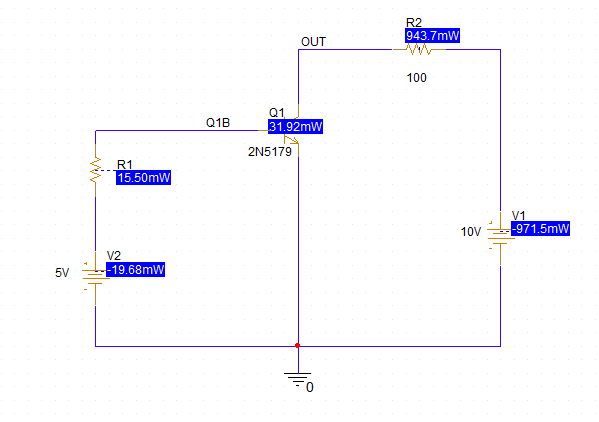
Step 14: View the bias point results. The power dissipated (positive) or supplied (negative) by each component is shown in the schematic.
Step 15: Select Enable Bias Power Display button to toggle the power display off.