Non-Ideal Components
This walk-through demonstrates use of the Modeling Application. After you complete this topic, you will be able to:
- Create and use a Piecewise Linear Source (PWL) in simulation
- Create and use a non-ideal component in simulation
To follow along, continue working with the design completed in PSpice Walk-through 5 or open the provided board file in the folder directory, PSpice Walk-through 6_Non-Ideal Components.
If materials were not downloaded in the beginning of the walk-through, they can be accessed through the Materials tab above for this lesson.
 Open in New Window
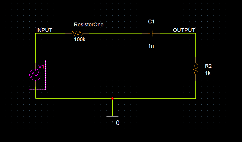
Step 1: Select V1 and press Delete on the keyboard.
Step 2: Select Place > PSpice Component > Modeling Application from the menu.
Note: The Modeling Application within PSpice allows you to quickly create models with your preferred parameters, attributes and tolerances and easily place them in your schematic.
Step 3: Select Sources > PWL.
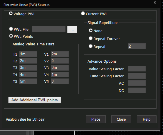
Step 4: Assign the above values to configure the time and voltage pairs.
Note: This will simulate a change in voltage at the specified times.
Step 5: Select Place.
Step 6: Click to place in the schematic.
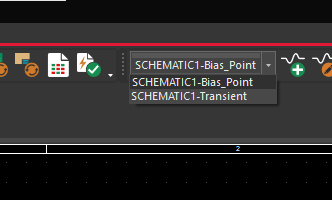
Step 7: From the existing simulation profiles, select Transient from the drop-down.
Note: Delete any existing probes by selecting the probes and pressing Delete on the keyboard.
Step 8: Select PSpice > Edit Simulation Profile from the menu.
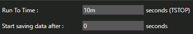
Step 9: Change the Run to Time to 10m.
Step 10: Select PSpice > Run from the menu.
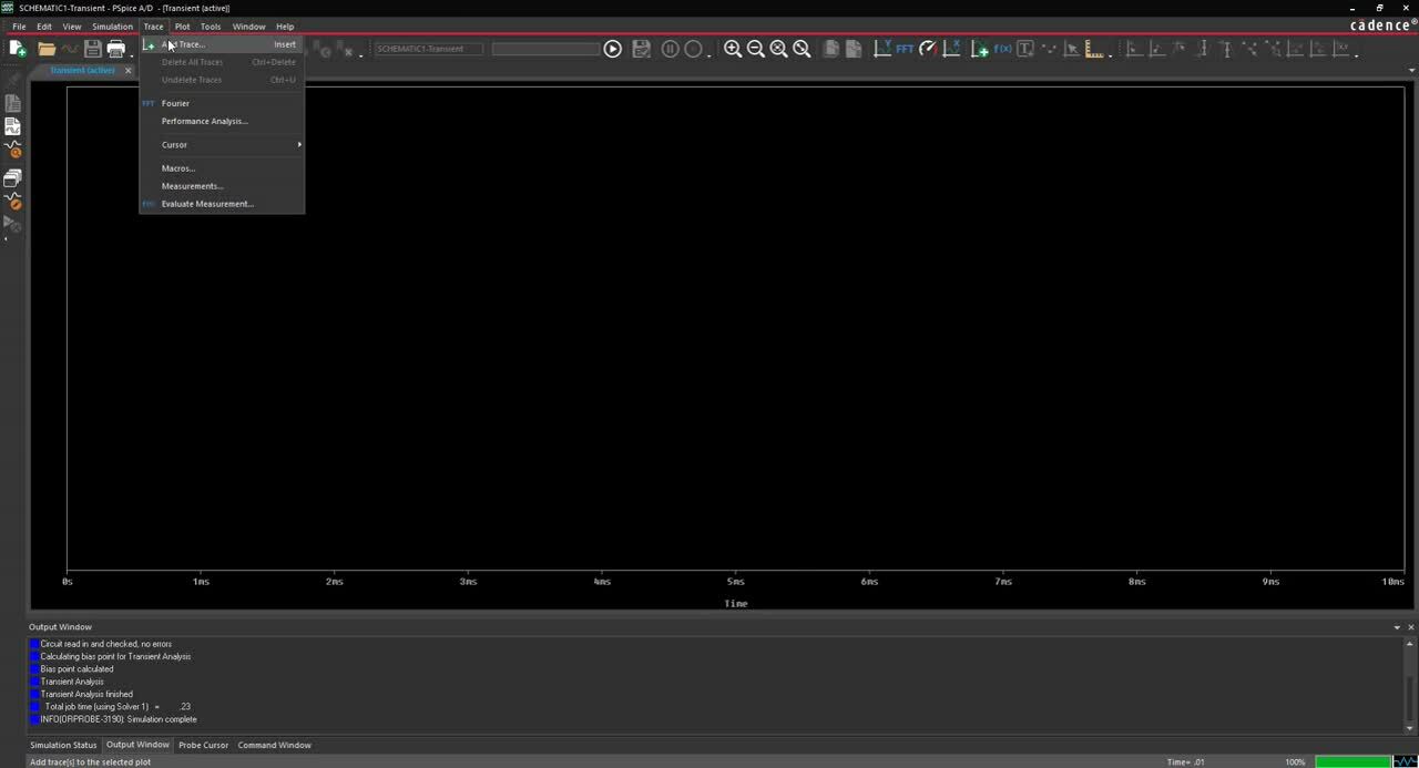
Step 11: In the plot window, select Trace > Add Trace from the menu.
Step 12: In Simulation Output Variables, select V(input) and V(output). Click OK.
Step 13: Back in the schematic, right click on V1 and select More > Edit Source Component.
Step 14: Select Repeat and set the value to 2.
Step 15: Select Update.
Step 16: Select PSpice > Run from the menu.
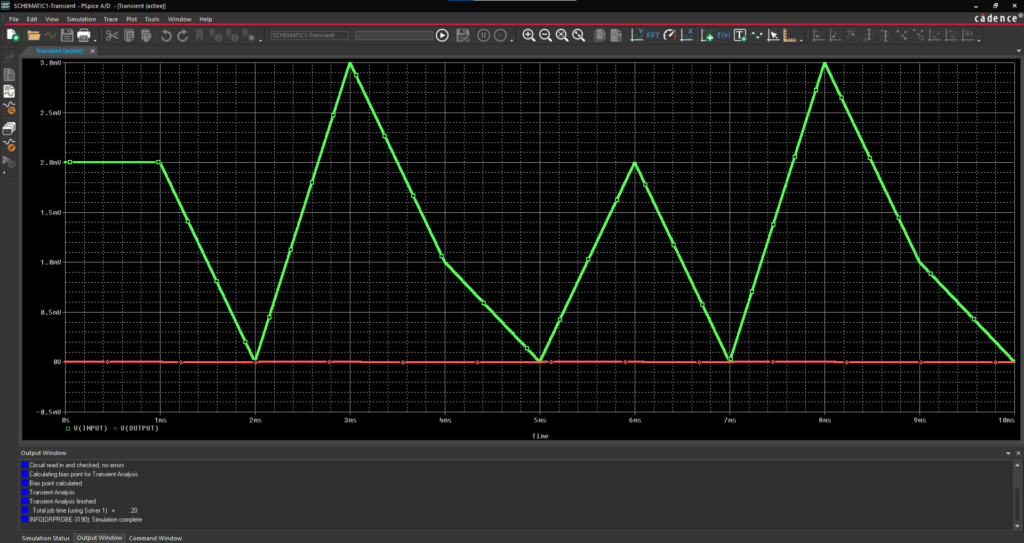
Step 17: View the repeated waveform in the Plot Window.
Step 18: Back in the schematic, select C1 and Delete.
Step 19: Select Passive > Capacitors from the Modeling Application.
Note: The capacitor found in the standard PSpice library is already completely charged. The Modeling Application includes fields where you can set tolerances and initial conditions as well as parasitic properties and temperature and voltage coefficients to create a non-ideal component.
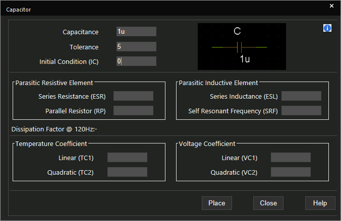
Step 20: Set the Tolerance to 5.
Step 21: Set the Initial Condition to 0.
Step 22: Select Place.
Step 23: Click to place in the schematic.
Step 24: Select PSpice > Run from the menu.
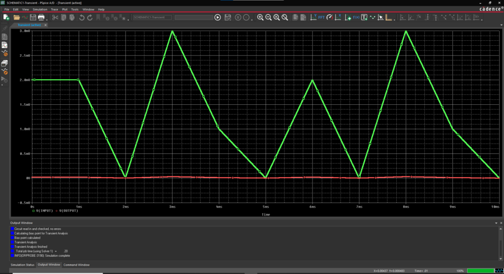
Step 25: In the Plot Window, view the results with the non-ideal capacitor.
Note: System Modules are also available in the Modeling Application. These include switches controlled by time voltage or current, single phase transformers, and voltage-controlled oscillators.