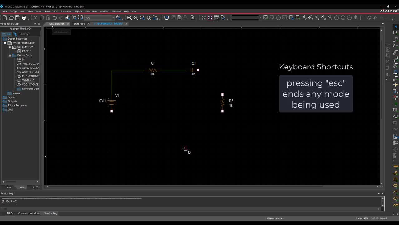
Wiring and Net Aliases
This walk-through demonstrates how to connect and wire PSpice parts. After you complete this topic, you will be able to:
- Place wires to complete your schematic
- Rename and edit schematic parts
- Assign net names
To follow along, continue working with the design completed in PSpice Walk-through 2 or open the provided board file in the folder directory, PSpice Walk-through 3_Wiring and Net Aliases.
 Open in New Window
Step 1: Click to select R2 and drag the component to the right of C1.
Step 2: Select Place > Wire from the menu (W).
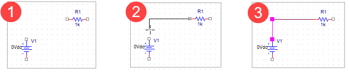
Step 3: Click to place the wire.
Note: If you make a mistake, right click and select End Mode. Select the wire and press Delete on the keyboard.
Step 4: Select Place > Auto Wire > Two Points from the menu.
Step 5: Click on one side of the component and then click the next component to connect it.
Note: Wires and components can be adjusted by clicking and dragging.
Step 6: Double click the R1 text.
Step 7: Change the value to ResistorOne. Click OK.
Step 8: Double click on the value 1k for ResistorOne.
Step 9: Change the value to 100k. Click OK.
Step 10: Select Place > Net Alias from the menu (N).
Note: Use of net aliases makes it easier to track the nets you want to observe in your probe window when doing simulations.
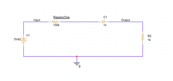
Step 11: Assign Input as the Alias and click OK.
Step 12: Click to place on the wire to the left of ResistorOne.
Step 13: Right click and select Edit Properties.
Step 14: Assign Output as the Alias and click OK.
Step 15: Click to place on the wire to the right of C1.
Step 16: Right click and select End Mode (ESC).