Capture Walk-through 8: Differential Pairs
This walk-through demonstrates how to define differential pairs in the schematic. This can also be completed during the PCB layout. After you complete the topic, you will be able to:
- Define differential pairs both manually and automatically
To follow along with this tutorial, continue with your design from Capture Walk-through 7 or use the included design file, CAPTURE TUTORIAL 8_DIFFERENTIAL PAIRS.DSN under the ‘materials’ tab.
 Open in New Window
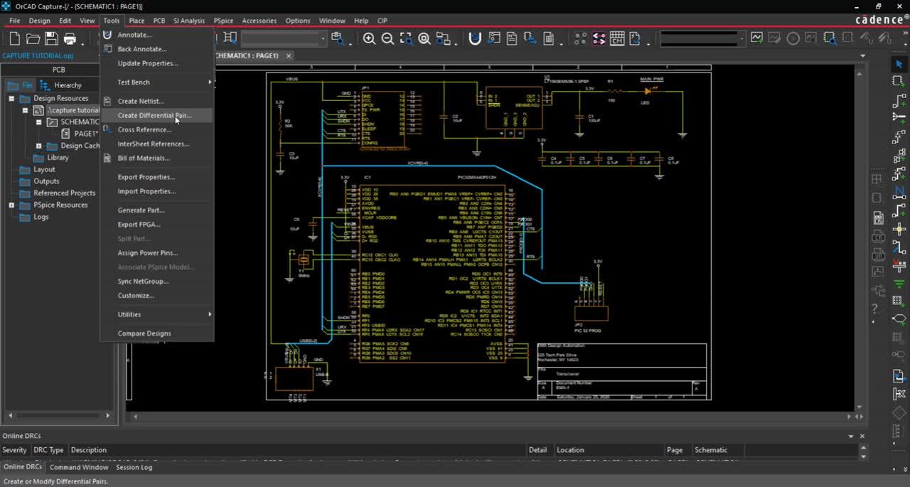
- In the project hierarchy, select the design file.
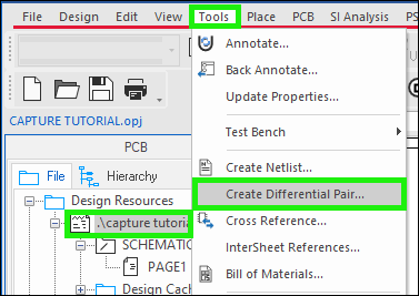
- Select Tools > Create Differential Pair from the menu.
- Select either the manual or automatic generation below:
Manual
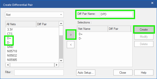
- Select D+ Net.
- Click the > button to select.
- Select D- Net.
- Click the > button to select.
- Assign DPD as the Diff Pair Name.
- Click Create.
Automatic
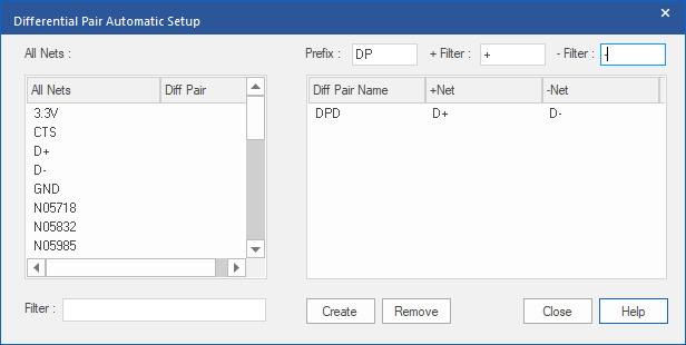
- Select Auto Setup.
- Assign DP as the Prefix.
- Assign + to + Filter.
- Assign – to – Filter.
- Click on the window to generate the differential pair.
- Select Create
- Close the differential pair window.