Beginning a Board Layout
This lesson will demonstrate how to initialize a board layout and configure the required settings for PCB layout in OrCAD X Presto.
To follow along, continue with the previously downloaded files or download the starting materials from the Materials tab of this lesson.
 Open in New Window
Creating a New Design
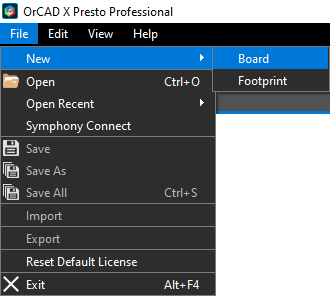
Step 1: Select File > New > Board from the menu or the New button in the Start page.
Step 2: Select File > Save As from the menu.
Step 3: Enter presto_tutorial.brd for the file name. In the materials provided, browse to the folder Presto Walkthrough\Allegro and click Save.
Configuring Design and Board Parameters
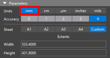
Step 4: In the Properties Panel under Parameters, select mm for Units to change the design units to millimeters.
Note: If the Properties panel is not visible, select View > Panels > Properties from the menu.
Step 5: Ensure the accuracy is set to 4. The accuracy is automatically set to four digits. The accuracy setting determines the number of significant digits allowed after a decimal point.
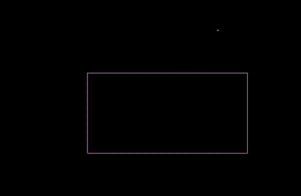
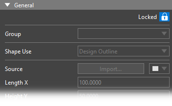
Step 6: In the PCB canvas, select the green board outline.
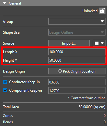
Step 7: Back in the Properties panel, set the Length X to 100 and the Height Y to 50.
Note: For more complex board designs, import the board outline or other mechanical features by selecting Import in the Properties Panel or ECO from the menu to select from the following import options:
- IDX
- DXF
- MCADX
To import the board outline or other mechanical features. To draw a custom outline in the PCB canvas, select ECO > Draw Design Outline from the menu.
Step 8: Enter 0.3 for the Conductor Keep-in.
Step 9: Enter 0.3 for the Component Keep-in.
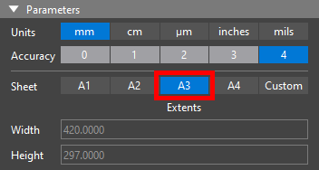
Step 10: In the Properties Panel under Parameters, select A3 for Sheet to change the sheet size to A3. The extents of the PCB canvas are adjusted automatically.
Step 11: Select the minus (-) key on the keyboard to zoom out to view the full extents of the PCB canvas.
Note: Another option to zoom out on the PCB canvas is to scroll down with the mouse wheel.
Moving the Board
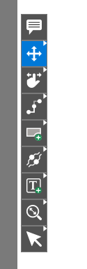
Step 12: Click to select the Move mode from the toolbar on the side of the canvas.
Step 13: Click to select the board outline. The board is attached to your cursor.
Step 14: Move the outline so the board is more centered in the canvas. Click to place the board when finished.
Note: The board can also be moved by entering coordinates in the X and Y locations in the Properties Panel.
Step 15: Click anywhere to deselect the board. Press Escape to return to the selection mode.
Defining the Board Origin
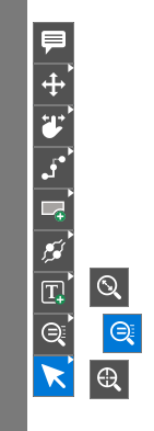
Step 16: Right-click the Zoom Icon on the toolbar and select Zoom Points.
Step 17: Click and drag to draw a small selection around the lower-left corner of the board.
Step 18: Under General in the Properties panel, select Pick Origin Location.
Step 19: Select the lower-left corner of the board. The origin is snapped to the corner vertex automatically.
Note: Snapping can be configured by selecting the Snapping menu at the top of the PCB canvas.
Step 20: Right-click the Zoom Icon on the toolbar and select Zoom Fit.
Step 21: In the Properties Panel, select the lock icon to lock the board outline.
Configuring the Board Stackup
Step 22: Select Tools > Cross Section from the menu.
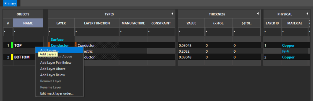
Step 23: The Cross-Section Editor window opens. Right-click on Top and select Add Layers.
Step 24: Select Below Conductor Top to create the plane below the top layer.
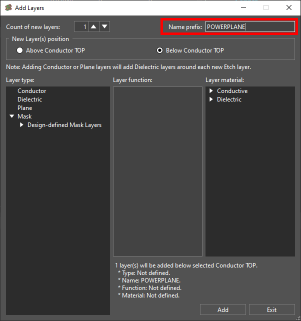
Step 25: Enter PowerPlane for the name prefix.
Step 26: Select Plane for the layer type. The layer function and layer material are selected automatically.
Step 27: Click Add and Exit to add the layer and its associated dielectrics.
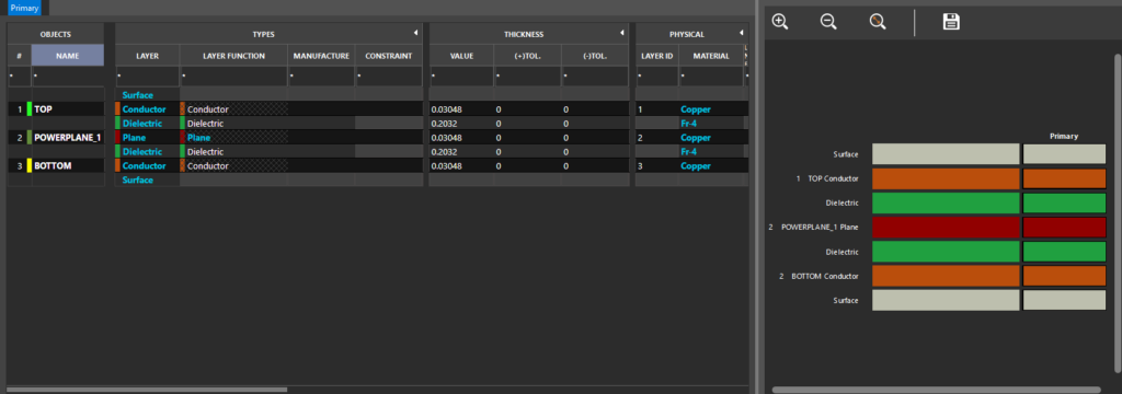
Note: The layer is added to the tabular and graphical stackups. Additional information can be added in the stackup including:
- Thickness
- Tolerance
- Material
- Fill-in Material
Step 28: Click OK to save the settings and close the window.
Syncing the Schematic
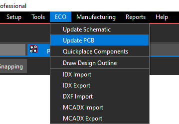
Step 29: Select ECO > Update PCB from the menu.
Step 30: The Update Layout window opens. Select the ellipsis for Schematic to select the netlist.
Step 31: Change the Files of Type selection filter to Capture Projects (opj). Select Capture_Tutorial.opj in the working directory. Click Open.
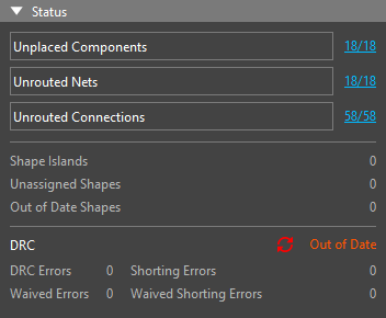
Step 32: Select Sync. The list of unplaced components, unrouted nets, and unrouted connections is updated.
Placing Mounting Holes
Step 33: Select Tools > Mechanical from the menu.
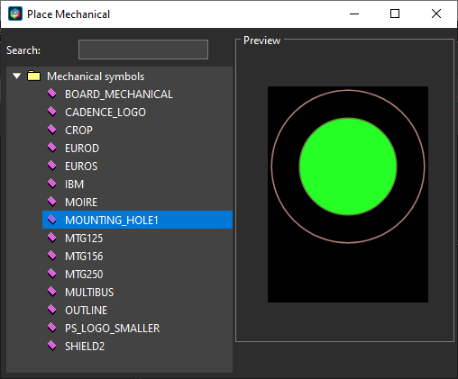
Step 34: The Place Mechanical window opens. Select MOUNTING_HOLE1, included with the design files.
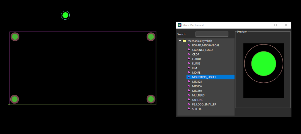
Step 35: With the window open, click to place a hole at each corner of the board. Close the window when finished.
Step 36: Select the top-left mounting hole.
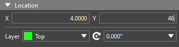
Step 37: In the Properties panel under Location, enter 4 for X and 46 for Y.
Step 38: Click the button with the lock icon to lock the symbol.
Note: When a mechanical symbol, board, or any object in the PCB canvas is locked, it cannot be moved or modified.
Step 39: Repeat steps 36-38 for the remaining three holes, with the following coordinates:
- Top Right: X = 96, Y = 46
- Bottom Left: X = 4, Y = 4
- Bottom Right: X = 96, Y = 4
Measuring the Mounting Holes
Step 40: Hold Alt on the keyboard and select the top left mounting hole. The rest of the board is shaded.
Step 41: Hover your mouse over the center of the bottom left mounting hole. The distance between the two is shown.
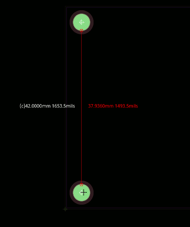
Edge-to-edge distance is shown in red, while center-to-center distance is shown in white. Hover your mouse over another object to measure the distance between the top left mounting hole and that object.