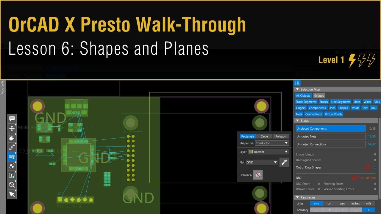
Creating Shapes and Planes
This lesson will demonstrate how to create shapes and planes in OrCAD X Presto.
To follow along, continue with the design from the previous lesson or download the starting materials from the Materials tab of this lesson.
 Open in New Window
Creating a Rectangular Ground Plane

Step 1: Select the Add Shape mode from the toolbar. Options are available to draw a rectangle, circle, or other polygon.
Step 2: In the resulting widget, select Bottom from the layer selection drop-down menu.
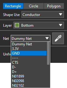
Step 3: Select GND as the net.
Step 4: Click and drag from the top-left corner of the board down and to the right. Cover approximately half of the board, then release to draw the shape.
Note: Only half of the board is covered with copper in this example to demonstrate additional features and capabilities for creating copper shapes and planes in OrCAD X Presto.
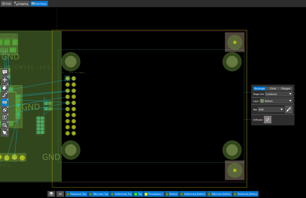
Step 5: Click and drag from the top-right corner of the board to cover the other half of the board. Two rectangles cover the bottom of the board in a ground plane. The shape is automatically trimmed such that it does not pass outside the board outline.
Merging Shapes

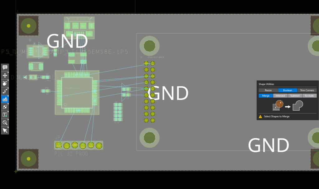
Step 6: Right-click the Add Shape mode in the toolbar and select Shape Utilities.
Step 7: Select Boolean in the resulting widget. The Shape Utilities mode can also be used to resize a shape, chamfer, or round the corners.
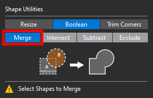
Step 8: Select Merge. You will be prompted to select the shapes to merge.
Step 9: Select the left, then the right rectangle. The rectangles will be merged into one.
Creating a Power Plane
Step 10: Select the Select mode from the toolbar.
Step 11: Select the ground plane. Right-click and select Copy.
Step 12: Right-click and select Paste Special.
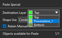
Step 13: In the Paste Special widget, change the Destination Layer to Powerplane_1.

Step 14: Click to place the copper pour to line up with the ground plane. Press Escape on the keyboard when finished.
Step 15: Click to select the new shape.
Note: Turn off the visibility for the Bottom plane in the Floating Layer toolbar to avoid accidentally selecting the bottom plane.
Step 16: In the Properties panel, set the Net to 3.3V to create a power plane.
Using Dynamic Healing
Step 17: Select the Move mode from the toolbar.
Step 18: Select JP2 (the 1×6 header) to move it. Click again to place it on the board.
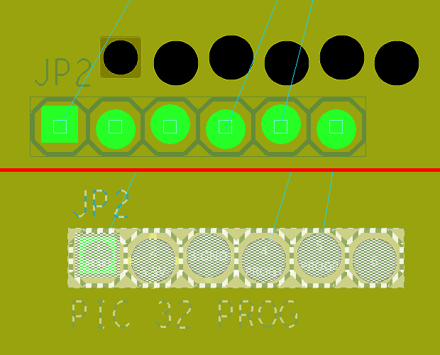
The Powerplane and bottom plane voids are adjusted automatically depending on the component’s location. Any old voids are “healed” with copper.