Lesson 10: Manufacturing Export
This walk-through demonstrates how to generate manufacturing export files in OrCAD PCB Designer 22.1 (2022). After you complete this topic, you will be able to:
- Generate IPC-2581 output
- Generate Gerber Artwork files
- Generate NC Drill file
To follow along, continue with the design from the previous lesson or use the downloaded materials.
If materials were not downloaded at the start of the walk-through, they can be accessed in the Materials tab of this lesson.
 Open in New Window
Generating the IPC-2581 File
Step 1: Select Manufacturing Deliverables > IPC-2581 from the Design Workflow.
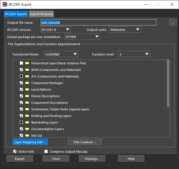
Step 2: The IPC2581 Export window opens. Select Layer Mapping Edit.
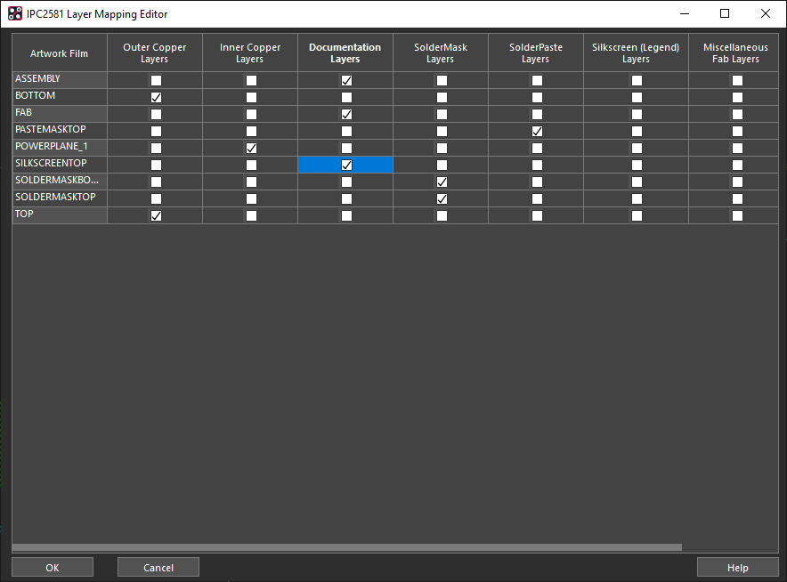
Step 3: A table of layer maps open. Select ASSEMBLY, FAB, and SILKSCREENTOP as Documentation Layers.
Step 4: Select SOLDERMASKBOTTOM and SOLDERMASKTOP as SolderMask layers.
Step 5: Select PASTEMASKTOP as a SolderPaste layer.
Step 6: Click OK to save the settings and close the window.
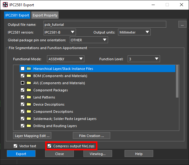
Step 7: Check the option for Compress Output File. Click Export to generate the file.
Step 8: An export log appears, showing general board information and any errors that may have occurred during the export. Close the log file.
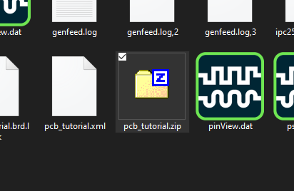
Note: The output file is saved as allegro\pcb_tutorial.zip in the working directory.
Generating Gerber Data
Step 9: Click Close to close the IPC2581 Export window.
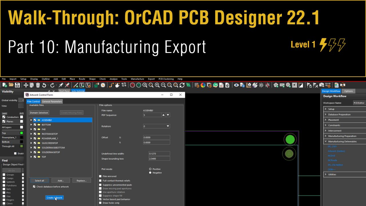
Step 10: Select Manufacturing Deliverables > Artwork (Gerber) from the Design Workflow.
Step 11: Select the General Parameters tab.
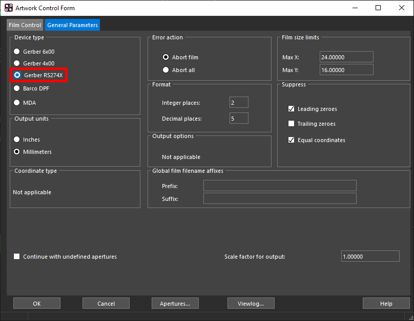
Step 12: Select Gerber RS274X for the Device Type.
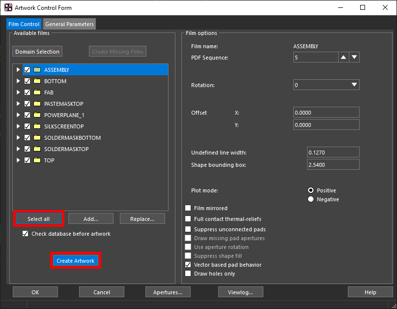
Step 13: Select the Film Control tab. Click Select All and Create Artwork.
Step 14: An export log appears, showing the film names and information, as well as any errors that may have occurred during the generation. Close the log file.
Step 15: Click OK to close the Artwork Control Form.
Generating the NC Drill Data
Step 16: Select Manufacturing Deliverables > NCDrill from the Design Workflow.
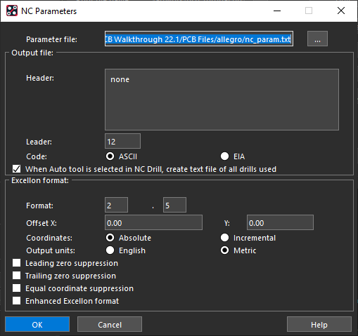
Step 17: Select Parameters. Use the default settings and click OK.
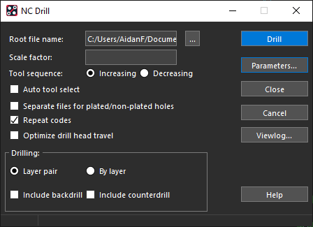
Step 18: Select Drill to generate the drill file.
Step 19: Click Close to close the window.