Lesson 11: AC Sweep
This walk-through will demonstrate how to create and run an AC Sweep analysis in OrCAD PSpice Designer 22.1. An AC sweep shows circuit response across a range of frequencies, similar to a discrete Fourier transform. After you complete this topic, you will be able to:
- Create an AC sweep simulation
- Run and analyze the AC sweep
- Perform a noise analysis
To follow along, continue with the design from the previous topic or use the provided materials.
If materials were not downloaded at the beginning of the walk-through, files for this lesson can be accessed through the materials tab above.
 Open in New Window
Creating an AC Sweep Simulation
Step 1: Select PSpice > New Simulation Profile from the menu.
Step 2: Name the simulation profile AC and click Create.
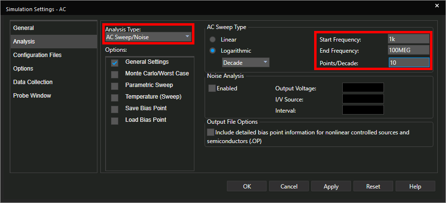
Step 3: In the Simulation Settings window, select AC Sweep/Noise from the Analysis Type dropdown.
Step 4: Enter the following simulation settings:
- Start Frequency: 1k
- End Frequency: 100MEG
- Points/Decade: 10
Step 5: Click OK to save the settings and close the window.
Note: Probes are not placed automatically when a new simulation is created. In this walk-through topic, the traces will be added when the simulation is complete.
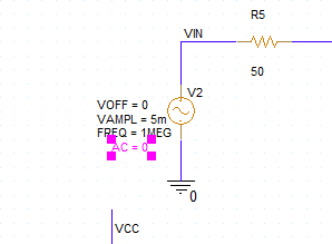
Step 6: Double-click the value AC = 0 on the sine source V2.
Note: An AC source component must be defined before the simulation can be run.
Step 7: Enter 1 for the value and click OK.
Running the AC Sweep
Step 8: Select PSpice > Run from the menu.
Step 9: View the results. The plot window opens to a blank canvas.
Step 10: Select Trace > Add Trace from the menu.
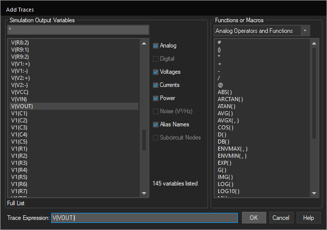
Step 11: The Add Traces window opens. Select trace V(VOUT) from the Simulation Output Variables list. Click OK.
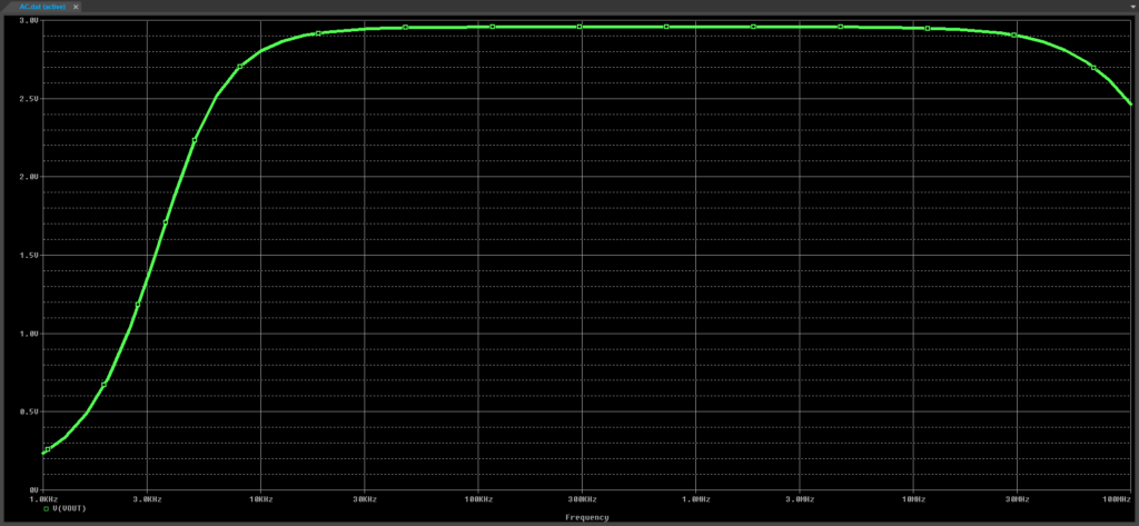
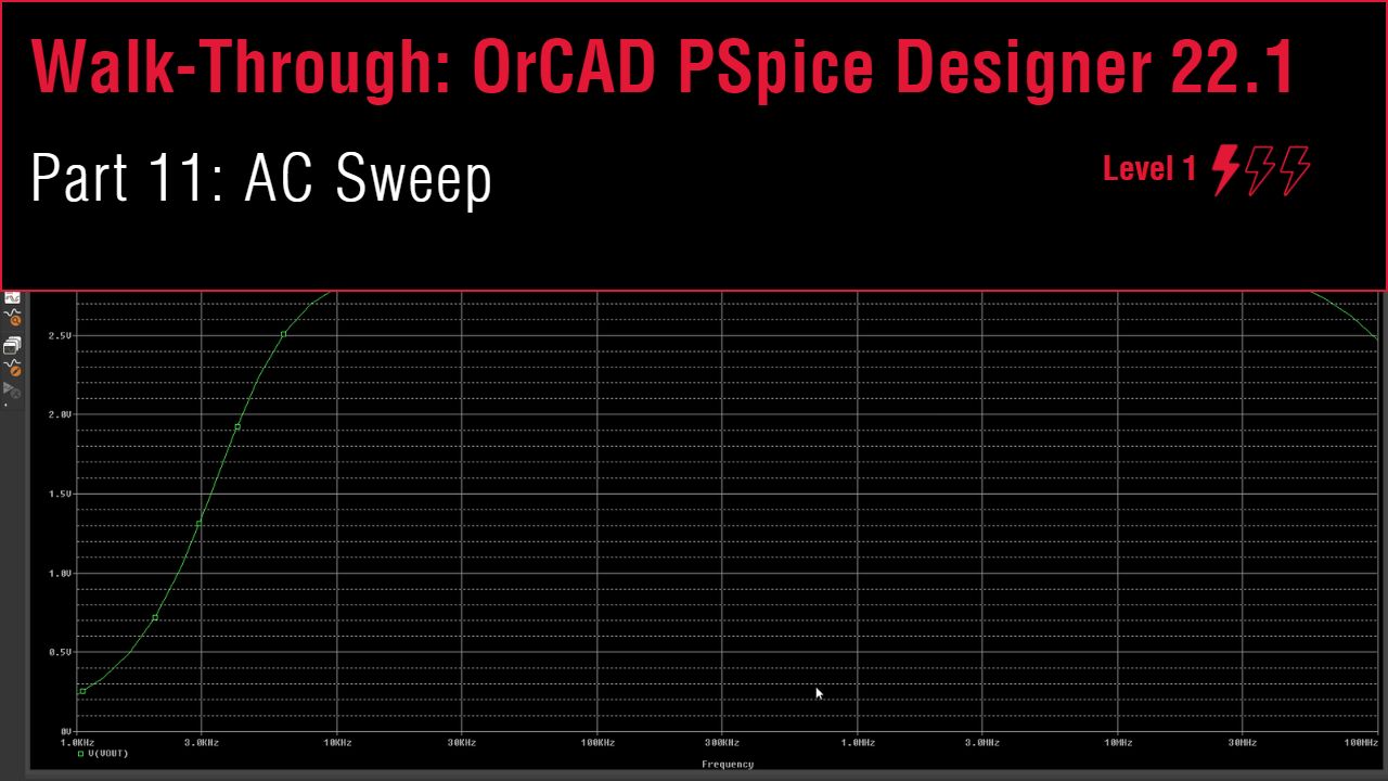
Step 12: View the plot. The output voltage has been plotted as a function of frequency.
Step 13: Close the plot window.
Performing a Noise Analysis
Step 14: Select PSpice > Edit Simulation Profile from the menu.
Step 15: Check Enabled under Noise Analysis.
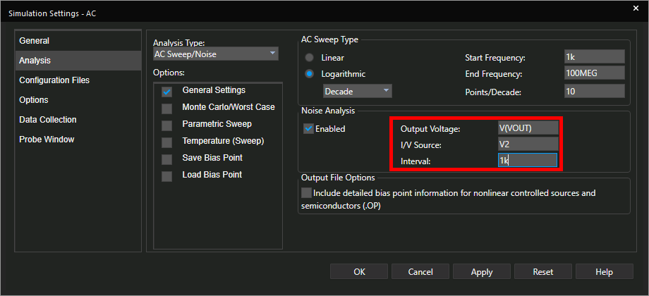
Step 16: Configure the following settings:
- Output Voltage: V(VOUT)
- I/V Source: V2
- Interval: 1k
Note: The Output Voltage determines the net at which the calculated noise is to be propagated to. I/V Source defines the input (current or voltage) source for the circuit. The Interval determines the frequency interval at which to calculate and record the noise contributions.
Step 17: Click OK to save the settings and close the window.
Step 18: Select PSpice > Run from the menu.
Note: The plot window will open to a blank plot.
Step 19: Select Trace > Add Trace from the menu.
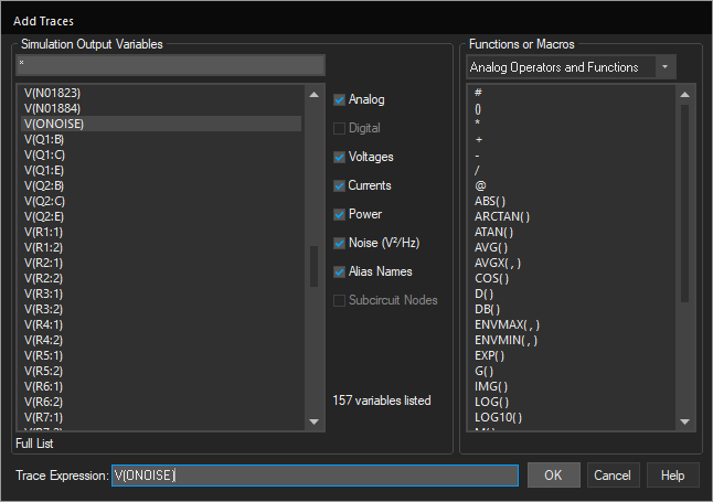
Step 20: Select V(ONOISE) from the Simulation Output Variables list. Click OK.
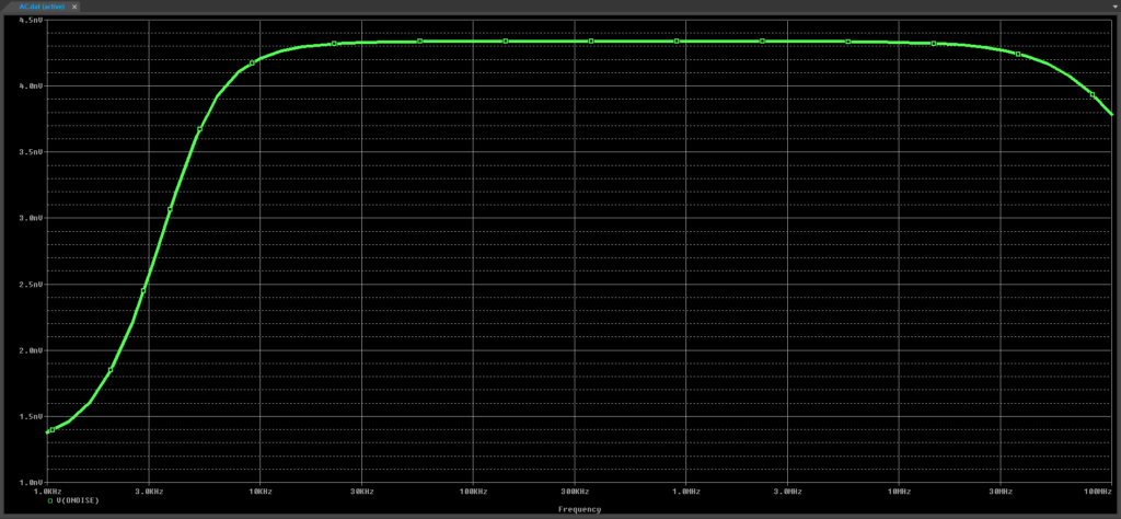
Step 21: View the results. The output noise has been plotted and follows a similar pattern compared to the original signal, but with lower magnitudes.