Lesson 11: Smart PDF
This walk-through demonstrates how to create a PDF and Smart PDF of your schematic design that you can view from a PDF reader using OrCAD Capture version 22.1 (2022). The Smart PDF includes a hierarchy that you can navigate through without losing your design IP. After you complete the topic, you will be able to:
- Generating a PDF
- Configure the first-time setup for a Smart PDF
- Generate a Smart PDF
To follow along, continue with the design from the last topic or use the provided design files. If the design files were not downloaded in the beginning of the Capture Walk-Through, the design files for this lesson can be found under the Materials tab.
 Open in New Window
Generating a Standard PDF
Step 1: Select the capture_tutorial.dsn file in the Project Hierarchy.
Step 2: Select File > Print from the menu.
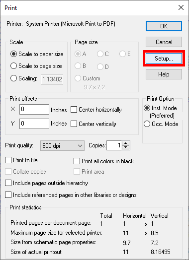
Step 3: The Print window opens. Select Setup to change the active printer.
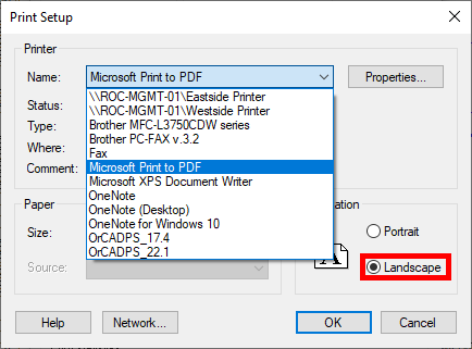
Step 4: Select Microsoft Print to PDF from the Name dropdown under Printer.
Step 5: Select Landscape for the orientation. Click OK.
Step 6: Click OK to start the print.
Step 7: Browse for a location to save the PDF. Enter a name and click Save.
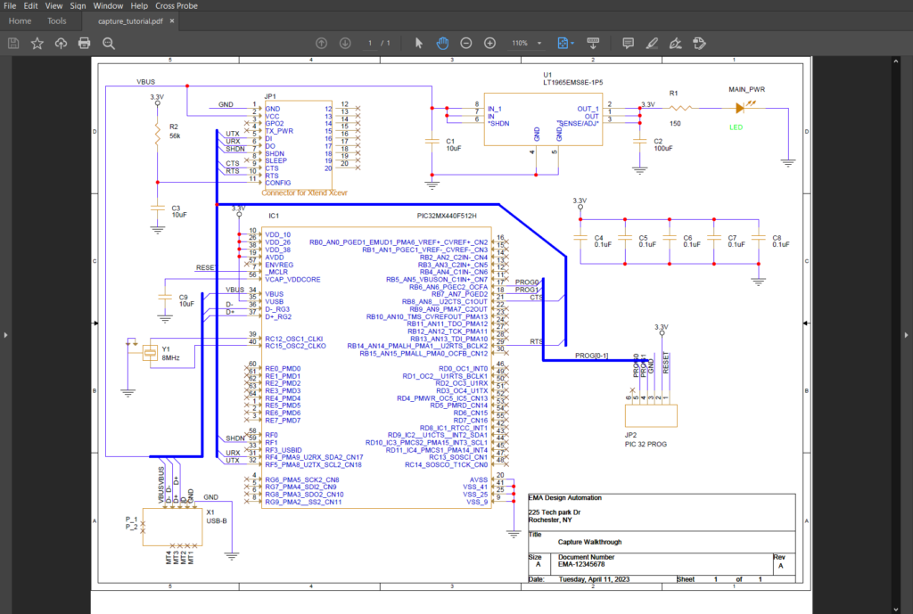
Step 8: Open File Explorer and browse to the location. Open the file in a PDF viewer of your choice. View the saved document.
Configuring Smart PDF Setup
Step 9: Select the capture_tutorial.dsn file in the Project Hierarchy.
Step 10: Select File > Export > PDF from the menu.
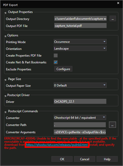
Step 11: If this is your first time generating a Smart PDF, red text will be visible. Click the link to open the download window.
Note: If the green text gswin64c.exe is available is visible, skip to Exporting the Smart PDF.
Downloading GhostScript
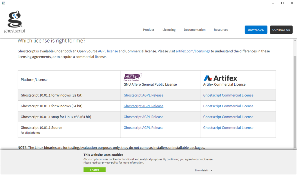
Step 12: Select the appropriate link to download GhostScript.
Step 13: The file browser opens. Browse to a location to save the installer.
Step 14: Run the installer and follow the on-screen prompts to install GhostScript.
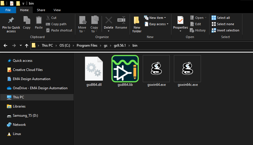
Step 15: Open File Explorer and browse to C:\Program Files\gs\[gs_version]\bin.
Step 16: Select the file path and press CTRL-C on the keyboard to copy.
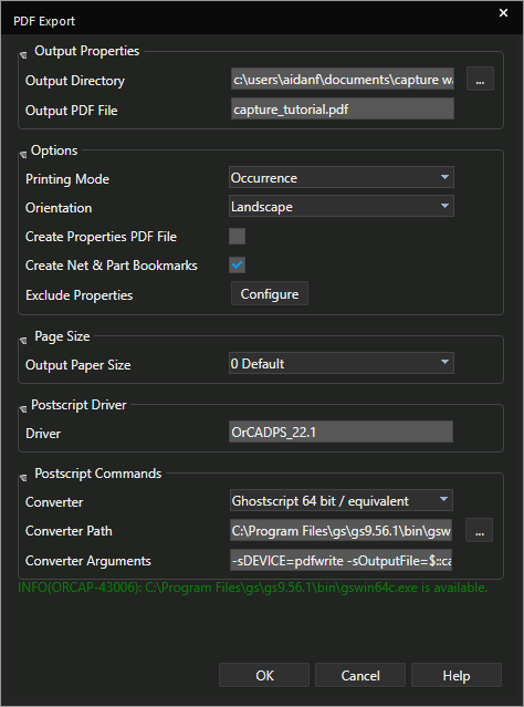
Step 17: Back in Capture, paste the file path into Converter Path.
Step 18: Enter \gswin64c.exe at the end to define the executable path. GhostScript has been configured and the Smart PDF can be generated.
Exporting the Smart PDF
Step 19: Under Output Properties, select the ellipses for Output Directory.
Step 20: The File Browser opens. Browse to a location to save the file and click Select Folder.
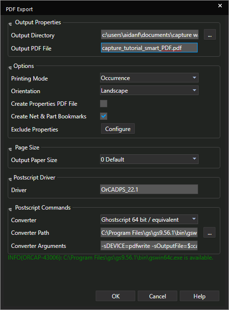
Step 21: Enter a name for the file into the Output PDF File field.
Step 22: Click OK to generate the Smart PDF. The PDF opens automatically in the default PDF viewer.
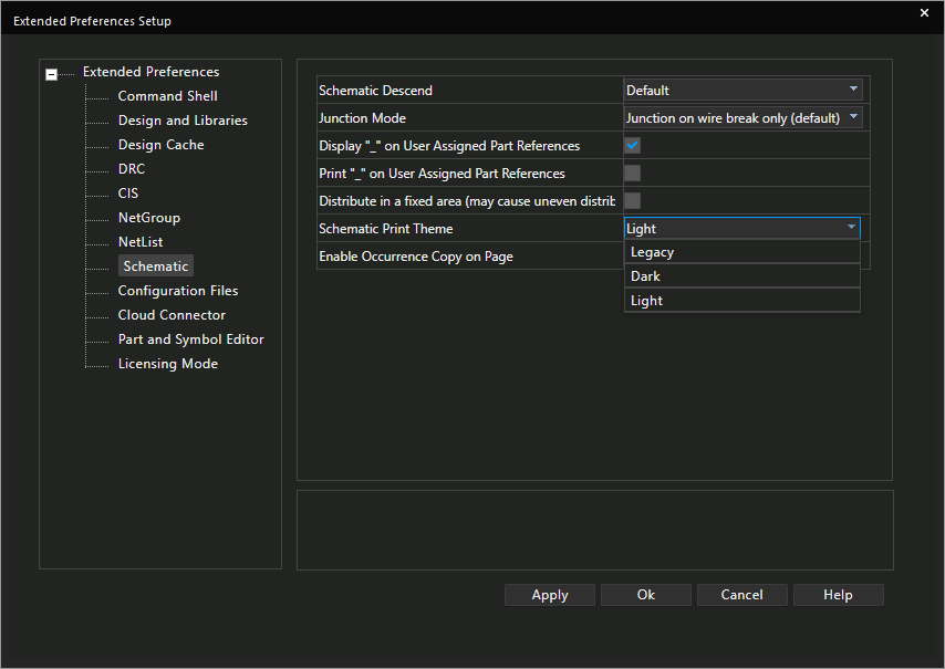
Note: By default, the schematic canvas will print in light mode regardless of your canvas settings. The PDF can be changed to print in dark mode or legacy mode by selecting Options > Extended Preferences from the menu. Select Schematic and change the schematic print theme to the desired settings.
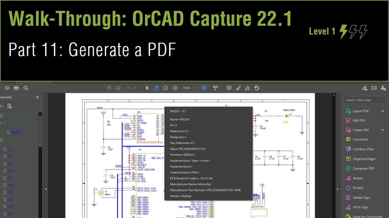
Navigating the PDF
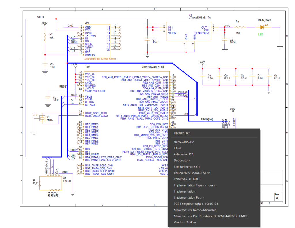
Step 23: Select a part to view its information, such as PCB footprint, reference designator, and the vendor added in Walkthrough 10.
Step 24: Open the Bookmarks panel.
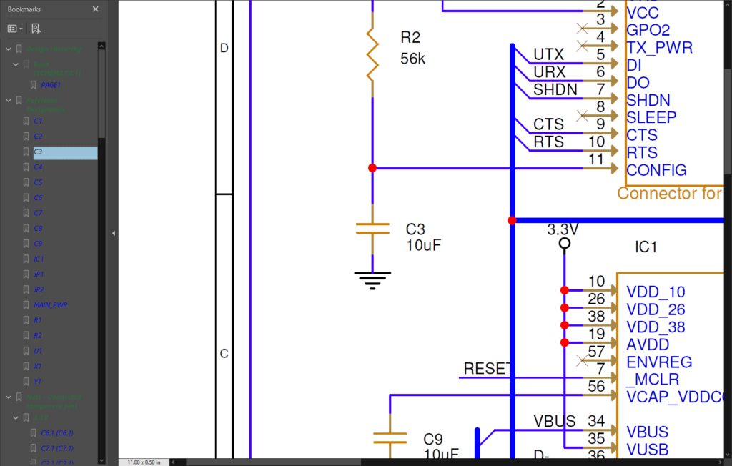
Step 25: Select a reference designator bookmark. The PDF will zoom into that part.
Note: The same can be done for pins and nets.