Lesson 15: Smoke Analysis
This walk-through will demonstrate how to perform smoke analysis to identify components that could potentially exceed their maximum ratings and fail when the circuit is fabricated. After you complete this topic, you will be able to:
- Add a variable list to the schematic
- Run Smoke Analysis
- Identify components that may fail in the field
- Improve reliability and longevity of PCB designs
To follow along, continue with the design from the previous topic or use the provided materials.
If materials were not downloaded at the beginning of the walk-through, files for this lesson can be accessed through the materials tab above.
 Open in New Window
Removing the ABMs
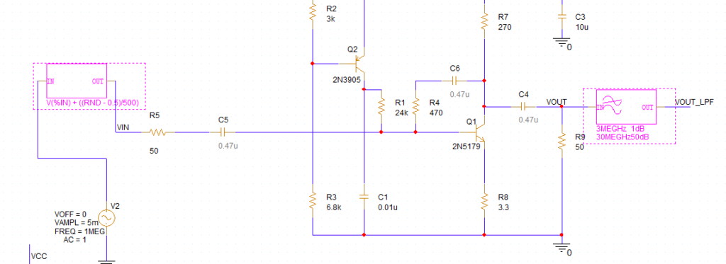
Step 1: Hold Ctrl on the keyboard and select the noise and LPF behavioral models.
Step 2: Press Delete on the keyboard.
Step 3: Select net VOUT_LPF. Press Delete on the keyboard.
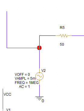
Step 4: Click and drag the open wire with alias VIN to connect it back to V2.
Step 5: Select any leftover wires and press Delete on the keyboard.
Adding Variables
Step 6: Select Place > Component from the menu.
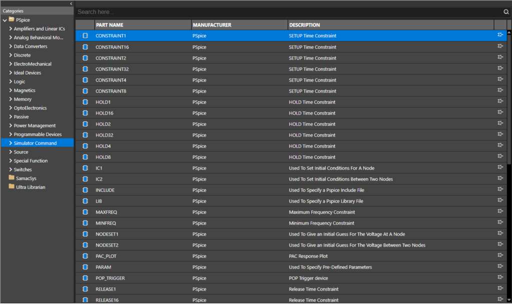
Step 7: Expand the PSpice category and select Simulator Command.
Step 8: Select Variables from the list. Right-click and select Place.
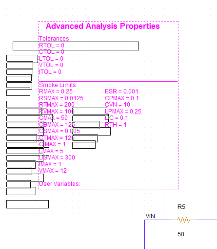
Step 9: Click to place the variable list in a blank portion of the schematic. Right-click and select End Mode.
Note: The tolerance and smoke limit variables are already defined.
Step 10: Double-click the value for RTOL under Tolerances. Set the value to 10 and click OK.
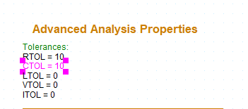
Step 11: Double-click the value for CTOL under Tolerances. Set the value to 10 and click OK.
Removing Non-Ideal Components
Step 12: Hold Ctrl on the keyboard and select non-ideal capacitors C4, C5, and C6. Press Delete on the keyboard.
Note: Non-ideal components can be identified by gray value text.
Step 13: Select Place > PSpice Part > Capacitor from the menu.
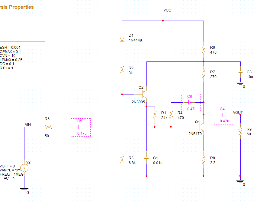
Step 14: Click to place ideal capacitors in the empty spaces. When finished, right-click and select End Mode.
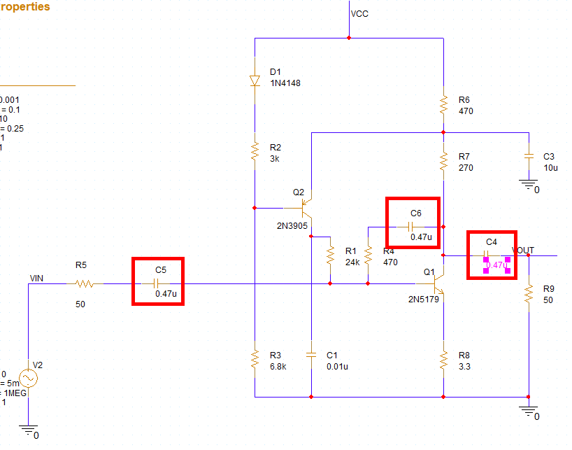
Step 15: Change the value for each new capacitor to 0.47u.
Note: Double-click the value, enter 0.47u, and click OK.
Running the Transient Simulation
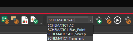
Step 16: Select SCHEMATIC1-Transient from the Active Simulation Profile drop-down menu at the top of the schematic.
Note: A transient simulation must be run before smoke analysis can be performed.
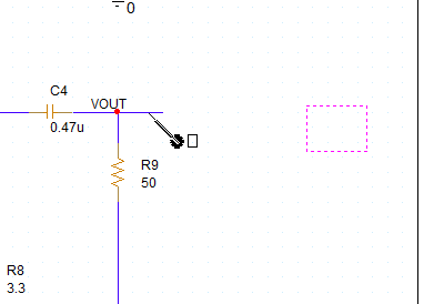
Step 17: The simulation probe formerly on V(VOUT_LPF) has been left floating. Click and drag the probe to place it on net V(VOUT).
Step 18: Select PSpice > Run from the menu. View the simulation results.
Note: The noise has been removed from the input and output waveforms.
Preparing Smoke Analysis
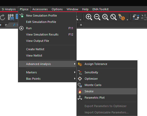
Step 19: Select PSpice > Advanced Analysis > Smoke from the menu.
Step 20: The Product Choices window opens. Select one of the available licenses and click OK.
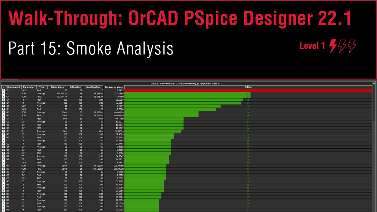
Step 21: The PSpice Advanced Analysis window opens to the Smoke table. Right-click in the table and select Hide Invalid Values.
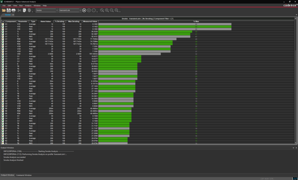
Note: This table shows the measured and maximum voltage and current values for each pin of each component. Green bars indicate values within range, yellow bars indicate values that are just under the maximum, and red bars indicate values that exceed the maximum. Gray bars indicate invalid values.
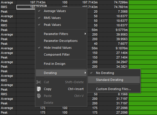
Step 22: Right-click and select Derating > Standard Derating.
Note: This will allow for a safety margin for measured values.
Step 23: Select Run > Start Smoke from the menu to run the smoke analysis.
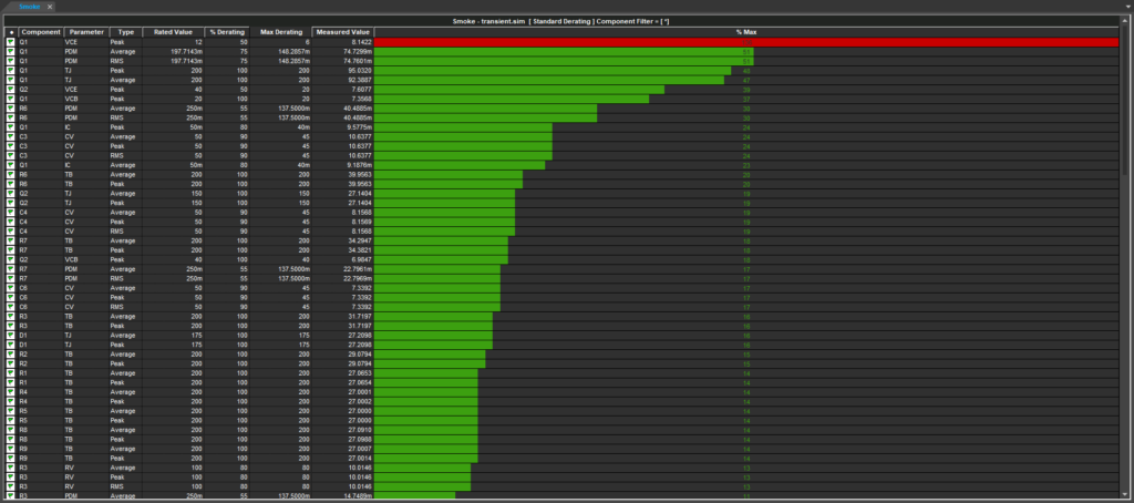
Step 24: View the results. The collector-emitter voltage on Q1 has exceeded its maximum derated value, as indicated by a red bar.
Step 25: Right-click the row for Q1 VCE and select Find in Design.
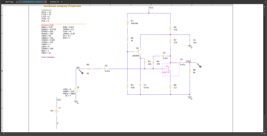
Note: This will highlight Q1 in the schematic.