Lesson 2: Creating Parts
This walk-through demonstrates several ways you can create and add parts to a Capture library in version 22.1 (2022). After you complete this topic, you will be able to:
- Copy library parts and paste them into a new design library
- Rename and edit a library part
- Create a new part and add it to your design library
To follow along, continue with the design from the last topic or use the provided design files. If the design files were not downloaded in the beginning of the Capture Walk-Through, the design files for this lesson can be found under the Materials tab.
 Open in New Window
Creating Parts from an Existing Library
Step 1: Select File > Open > Library from the menu.
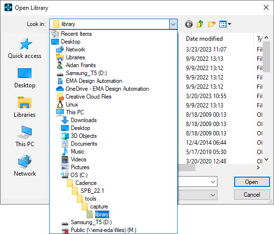
Step 2: Browse to the default Capture library path: C:\Cadence\SPB_22.1\tools\capture\library.
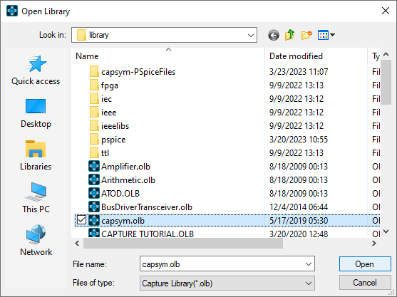
Step 3: Select the capsym.olb library and click Open. The library will be loaded into the project.
Note: Click on the arrow located in the right of the library, to change the view of the window: docked, floating, or a tabbed document.
Step 4: Hold CTRL on the keyboard and click GND_POWER and TitleBlock3 to select them.
Step 5: Press CTRL-C on the keyboard to copy.
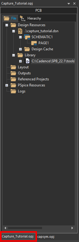
Step 6: Select the Capture_Tutorial.opj tab to open the walk-through project hierarchy.
Step 7: Right-click the CAPTURETUTORIAL.OLB library and select Paste to add the ground and title block.
Step 8: Expand the library to see the parts.
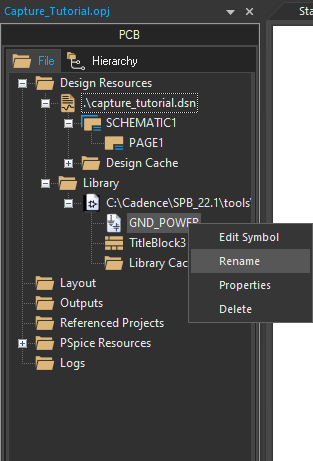
Step 9: Right-click GND_POWER and select Rename.
Step 10: Enter the name GND and click OK.
Step 11: Right-click TitleBlock3 and select Rename. Enter the name TitleBlock and click OK.
Creating Parts from Scratch
Step 12: Right-click the CAPTURETUTORIAL.OLB library and select New Part.
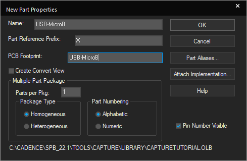
Step 13: Enter the following information:
- Name: USB-MicroB
- Part Reference Prefix: X
- PCB Footprint: USB-MicroB
Note: Use TAB on the keyboard to quickly go to the next field.
Step 14: Click OK. The Part Editor tab opens.
Step 15: Click the boundary to display vertices.
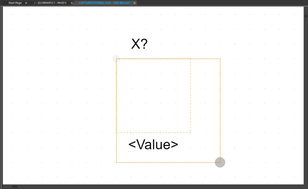
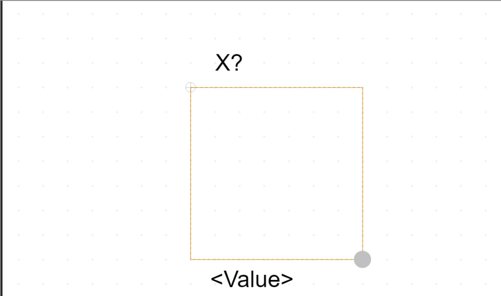
Step 16: Click and drag the lower-right vertex to resize the boundary box to seven-by-seven units.
Step 17: Select Place > Rectangle from the menu.
Step 18: Click to start drawing the rectangle and click again to finish. Right-click and select End Mode.
Step 19: Select Place > Pin from the menu.
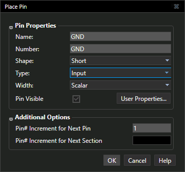
Step 20: Define the pin properties as follows and click OK to place.
- Name: GND
- Number: GND
- Shape: Short
- Type: Input
Step 21: Click a location on the part boundary to place the pin.
Step 22: Press Shift-G on the keyboard to re-open the Place Pin window.
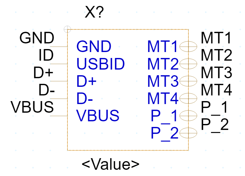
Step 23: Enter the pin values and place the pins using the properties below:
| Name | Number | Shape | Type |
|---|---|---|---|
| USBID | ID | Short | Input |
| D+ | D+ | Short | Input |
| D- | D- | Short | Input |
| VBUS | VBUS | Short | Input |
| MT1 | MT1 | Zero Length | Bi-Directional |
| MT2 | MT2 | Zero Length | Bi-Directional |
| MT3 | MT3 | Zero Length | Bi-Directional |
| MT4 | MT4 | Zero Length | Bi-Directional |
| P_1 | P_1 | Zero Length | Bi-Directional |
| P_2 | P_2 | Zero Length | Bi-Directional |
Note: When the pin ends in a number the next pin placed will be sequential. You can continue to click and place MT1 to MT4 and P_1 to P_2 without editing properties between pins.
Step 24: Right-click and select End Mode when finished.
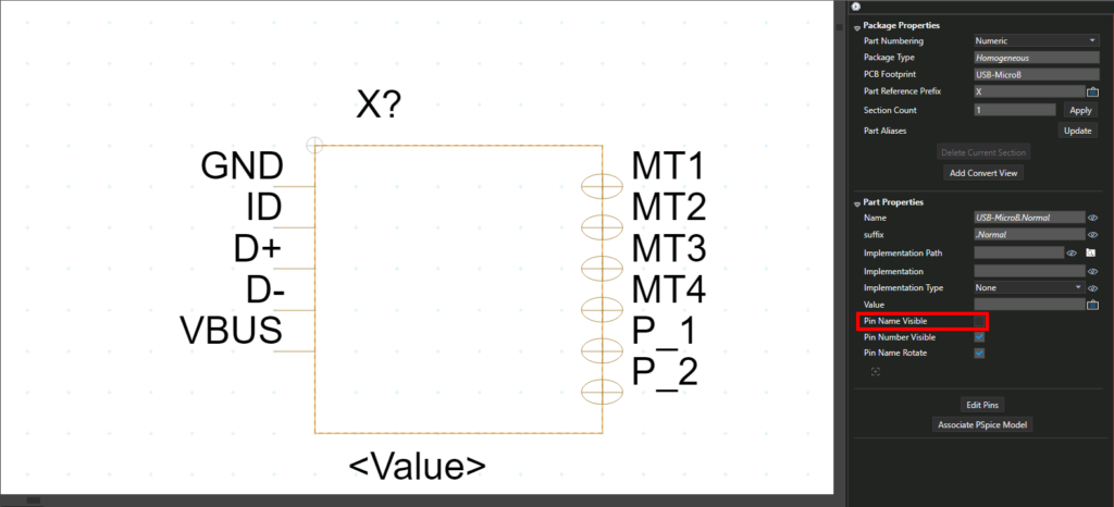
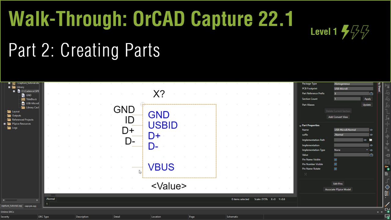
Step 25: In the property sheet, de-select the Pin Name Visible checkbox.
Step 26: Select the <Value> text. Click and drag to move the text to a new location.
Note: Right-click and select Rotate to rotate the text.
Step 27: Double-click the text.
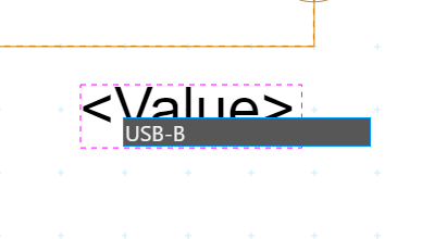
Step 28: Enter USB-B for the value and press Enter.
Step 29: Right-click the part tab and select Save to save the part.
Step 30: Right-click the part tab and select Close.