Lesson 2: Mechanical Symbols
This walk-through demonstrates how to create and place mechanical symbols in OrCAD PCB Designer 22.1 (2022). After you complete this topic, you will be able to:
- Create a mounting hole
- Place mechanical symbols on your PCB
To follow along, continue with the design from the previous lesson or use the downloaded materials.
If materials were not downloaded at the start of the walk-through, they can be accessed in the Materials tab of this lesson.
 Open in New Window
Creating the New Symbol
Note: While there are mechanical symbols included in the default libraries, the purpose of this walk-through is to provide an example of creating a mechanical symbol.
Step 1: Select File > New from the menu.
Note: Included in the design files is a mechanical library. If you do not want to create the mechanical symbol, copy the .bsm and .dra files included in the mechanical library and paste the files in the standard PCB footprint library: C:\Cadence\SPB_22.1\share\pcb\pcb_lib\symbols

Step 2: Select Mechanical Symbol from the Drawing Type list.
Step 3: Name the drawing Mounting_Hole1.
Step 4: Select Browse.
Step 5: Browse to the default location C:\Cadence\SPB_22.1\share\pcb\pcb_lib\symbols. Select Open.
Step 6: Click OK to create the new drawing.
Step 7: The Create a New Design window opens. Leave the default settings and click OK.
Configuring the Design Canvas
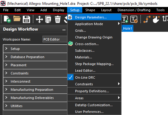
Step 8: Select Setup > Design Parameters from the menu.
Step 9: Select the Design tab.
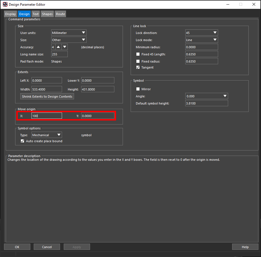
Step 10: Enter 100 into the X and Y fields under Move Origin to move the origin. Click OK.
Note: This will allow the padstack to be placed.
Placing the Padstack
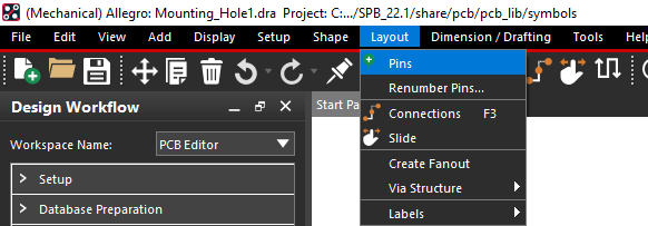
Step 11: Select Layout > Pins from the menu.
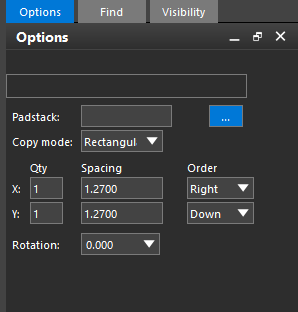
Step 12: In the Options panel, select the ellipsis for Padstack to browse for a padstack.
Step 13: Select Hole150 from the padstack list and click OK.
Note: If you do not see the command window, select View > Windows > Command from the menu.
Step 14: Enter x 0 0 into the command window. Press Enter to place the padstack at the origin.
Note: If an error appears that the pin cannot be placed outside of the drawing extents the origin needs to be changed. Follow instructions in the Configuring the Canvas section.
Step 15: Use the mouse wheel or the Zoom In button on the toolbar to zoom into the padstack.
Creating the Keepouts
Step 16: Select Shape > Circular from the menu.
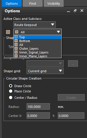
Step 17: In the Options panel, select Route Keepout from the Active Class dropdown and Top from the Active Subclass dropdown.
Step 18: Click to place the route keepout at the origin.
Step 19: Enter x 3 into the command window and press Enter.
Note: This sets the radius of the circle. You can also drag the circle to the desired size and click to place.
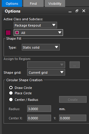
Step 20: In the Options panel, select Package Keepout from the Active Class dropdown and All from the Active Subclass dropdown.
Step 21: Select Place Circle under Circular Shape Creation.
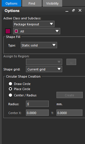
Step 22: Enter 3 into the Radius field.
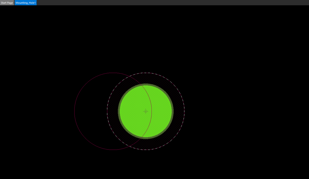
Step 23: Click to place the package keepout in the center of the padstack.
Step 24: Right-click and select Done.
Step 25: Select File > Save from the menu. Click Yes when prompted to overwrite the symbol.
Placing the Mounting Holes
Step 26: Select File > Recent Designs and select the PCB_TUTORIAL.brd design to reopen it.
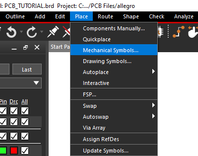
Step 27: Select Place > Mechanical Symbols from the menu.
Step 28: In the Placement List, select Mechanical Symbols from the dropdown if not already selected.
Step 29: Select the Advanced Settings tab.
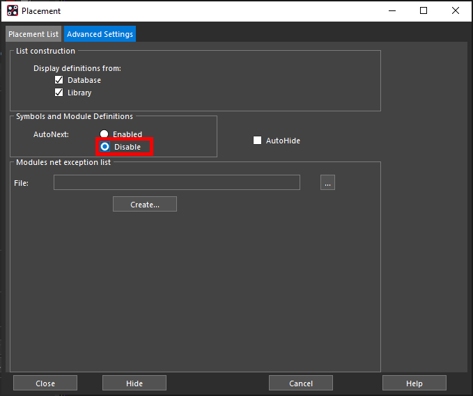
Step 30: Under Symbols and Module Definitions, select Disable for AutoNext.
Note: This will allow you to place all four holes consecutively.
Step 31: Select the Placement List tab.
Step 32: Check the option for MOUNTING_HOLE1.
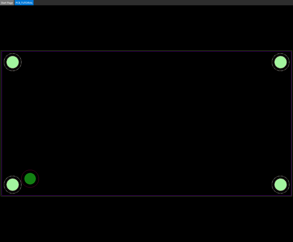
Step 33: Click to place a mounting hole in each corner of the board.
Step 34: When finished, select Close in the placement window.
Note: Do not close the window any other way, or the holes will not be placed.