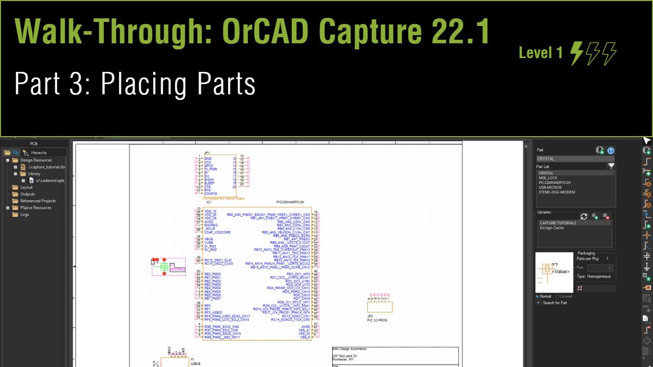
Lesson 3: Placing Parts
This walk-through demonstrates several techniques you can use to search for parts and place them on your schematic in OrCAD Capture version 22.1 (2022). After you complete this topic, you will be able to:
- Add a library to your Capture project
- Place a title block, components, ground, and power on a schematic page
- Search for parts in the default Capture libraries
- Place a part from the Unified Search
To follow along, continue with the design from the last topic or use the provided design files. If the design files were not downloaded in the beginning of the Capture Walk-Through, the design files for this lesson can be found under the Materials tab.
 Open in New Window
Loading an Existing Library
Step 1: In the project hierarchy, right-click Library and select Add File.
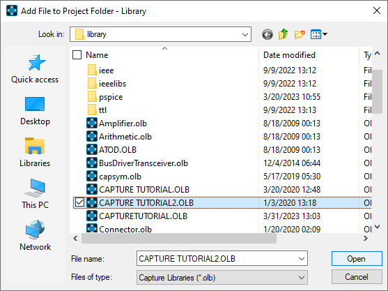
Step 2: The file browser opens to the default library folder. Select Capture Tutorial2.OLB.
Step 3: Right-click the first Capture Tutorial library and select Cut.
Placing a Title Block
Step 4: Select Options > Design Template from the menu.
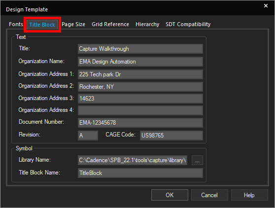
Step 5: Select the Title Block tab.
Step 6: Select the ellipsis for Library Name under Symbol.
Step 7: Select Capture Tutorial2.OLB and click Open.
Step 8: Click OK.
Step 9: Select Place > Title Block from the menu.
Step 10: The Place Title Block window opens. Select Add Library.
Step 11: Browse to and select Capture Tutorial2.OLB and click Open.
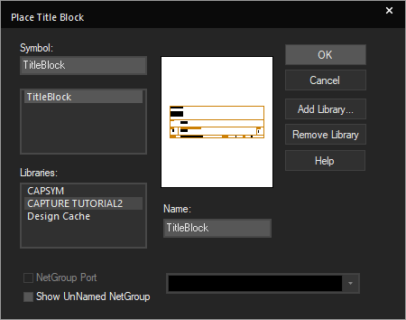
Step 12: The Capture tutorial library is automatically selected. Select TitleBlock and click OK.
Step 13: Click to place the title block in the lower-right corner of the schematic. Right-click and select End Mode.
Confirming Part Reference Designator Assignment
Step 14: Select Options > Preferences from the menu.
Step 15: Select the Miscellaneous tab.
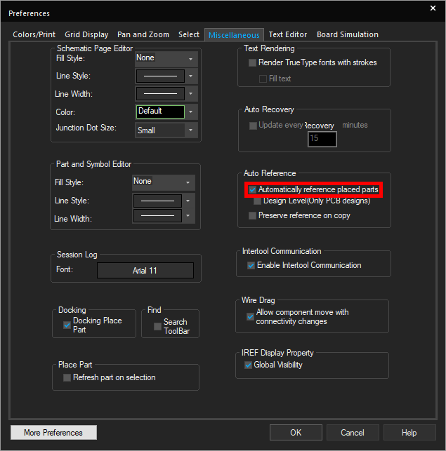
Step 16: Confirm that Automatically Reference Placed Parts under Auto Reference is checked. Click OK.
Placing Library Parts
Step 17: Select Place > Part from the menu or press P on the keyboard.
Step 18: Select Capture Tutorial2 from the libraries list.
Step 19: Select PIC32MX440F512H from the part list.
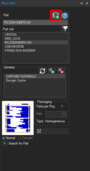
Step 20: Select the Place Part button or double-click the part.
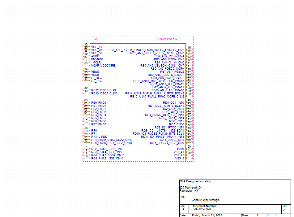
Step 21: Click to place the part on the schematic. Right-click and select End Mode when finished.
Step 22: Repeat steps 19-21 to place JP1, JP2, X1, and Y1 in the schematic, using the table below and the provided Capture Tutorial.pdf as a reference. The table below provides the part numbers and corresponding reference designators.
| Part | Reference Designator |
|---|---|
| XTEND-DIGI-MODEM | JP1 |
| M06_LOCK | JP2 |
| PIC32MX440F512H | IC1 |
| USB-MICROB | X1 |
| CRYSTAL | Y1 |
Note: To rotate a part during placement, press R on the keyboard, or right-click and select Rotate. This can also be completed once the part is placed.
Placing Parts from Included Libraries
Step 23: Click the plus sign in the Place Part panel to expand Search for Part.
Step 24: Verify that the search path is set to the default Capture library: C:\Cadence\SPB_22.1\tools\capture\library.
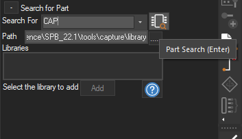
Step 25: Enter CAP into the Search For field and click the Part Search icon.
Step 26: Select the discrete library, labeled as CAP/Discrete.olb.
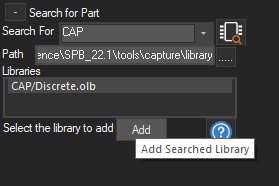
Step 27: Click Add.
Note: This has added the library and the library can now be searched in the parts window. To add multiple libraries, click the Add Library button. Select all default libraries and Open. This will allow you to search all of the libraries in the Place Part panel. Click the Remove Library button to delete a library from the parts window.
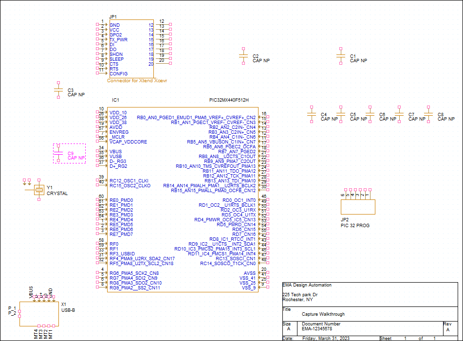
Step 28: Select CAP NP to place a non-polarized capacitor. Double-click the part or click the Place Part icon.
Step 29: Click to place the capacitors according to the provided schematic. Right-click and select End Mode when finished.
Note: When completed, make sure nine capacitors have been placed.
Step 30: Enter Resistor into the top search field and press Enter to search.

Step 31: Double-click RESISTOR to place a resistor.
Step 32: Click to place the resistors according to the provided schematic. Right-click and select End Mode when finished.
Note: When completed, make sure two resistors have been placed.
Step 33: Enter LED into the top search field and press Enter to search.
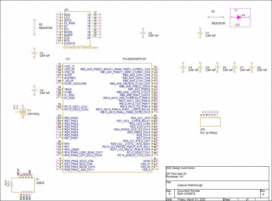
Step 34: Double-click LED to place an LED.
Step 35: Click to place the LED according to the schematic. Right-click and select End Mode when finished.
Placing Power and Ground
Step 36: Select Place > Ground from the menu.
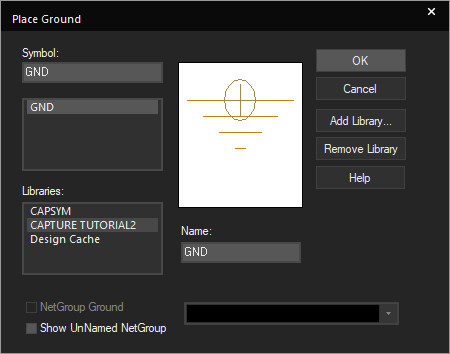
Step 37: Select GND and click OK.
Step 38: Click to place the ground according to the provided schematic. Right-click and select End Mode when finished.
Note: When completed, there should be nine occurrences of the ground symbol.
Step 39: Select Place > Power from the menu.
Step 40: Select capsym from the Libraries list.
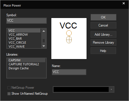
Step 41: Select VCC from the symbol list and click OK.
Step 42: Click to place the power according to the provided schematic. Right-click and select End Mode when finished.
Note: When completed, there should be four occurrences of the power symbol.
Placing Parts from a Search
Step 43: Select Place > Component from the menu.
Note: This activates the unified search, which allows you to search PSpice, Ultra Librarian, and Samacsys parts in a centralized location directly in OrCAD Capture.
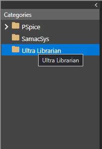
Step 44: Select the Ultra Librarian category from the Categories sidebar.
Step 45: Log in by entering your Ultra Librarian credentials. Click OK.
Step 46: Search for LT1965EM.
Note: The unified search results show you the:
- Manufacturer
- Part number
- Description
- Availability of the symbol, footprint, and 3D model
A part can only be placed in your design when both the symbol and footprint are available.
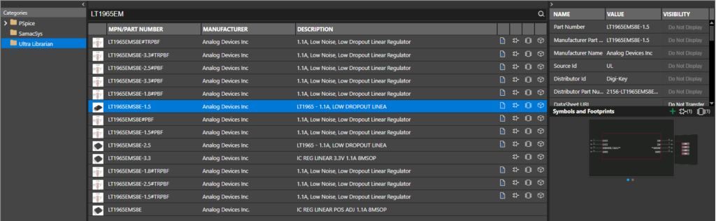
Step 47: Select part LT1965EMS8E-1.5 to view additional information.
Step 48: Right-click and select Place. The part will be downloaded and attached to your cursor.
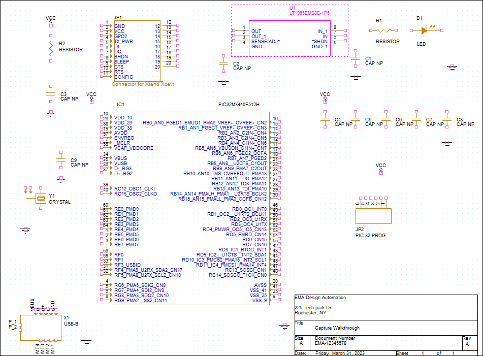
Step 49: Click to place the part in the schematic. Right-click and select End Mode.
Note: With your cursor clear, click and drag to move any components in the way.
Step 50: Select the newly placed part. Right-click and select Edit Part.
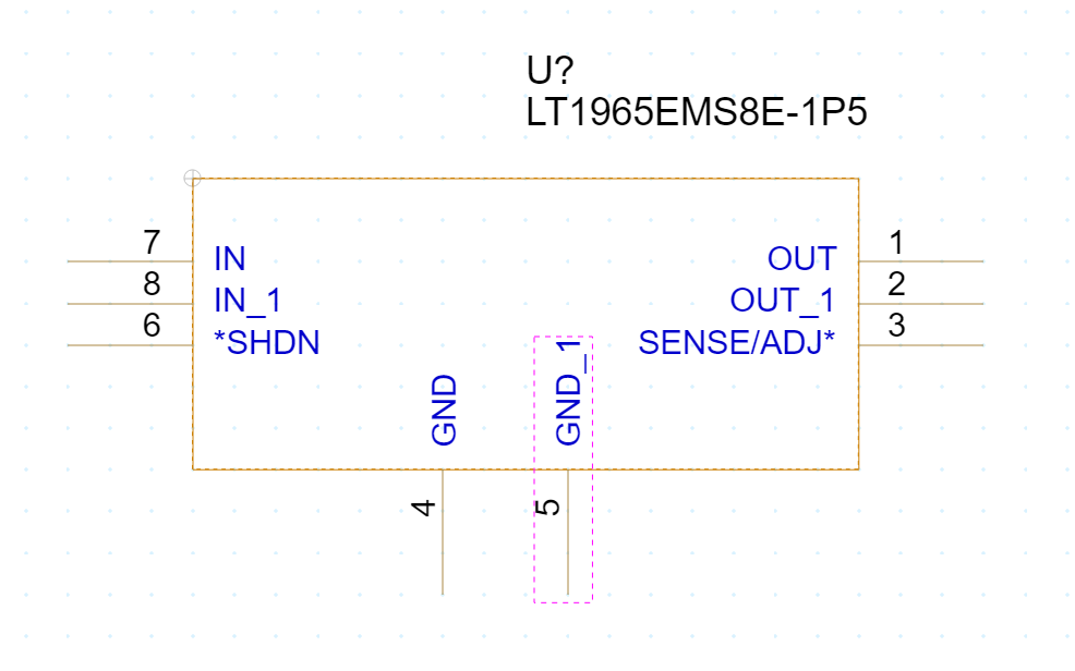
Step 51: Click and drag to rearrange the pins such that:
- The ground pins are on the bottom
- The OUT and SENSE/ADJ pins are on the right
- The IN and SHDN pins are on the left
Note: If you have an extra EPAD or PAD pin, place it on the bottom with the grounds.
Step 52: Click to close the tab. A prompt will appear to update only the current part instance or all instances in the design. Select Update All. Answer Yes to any prompts that follow.