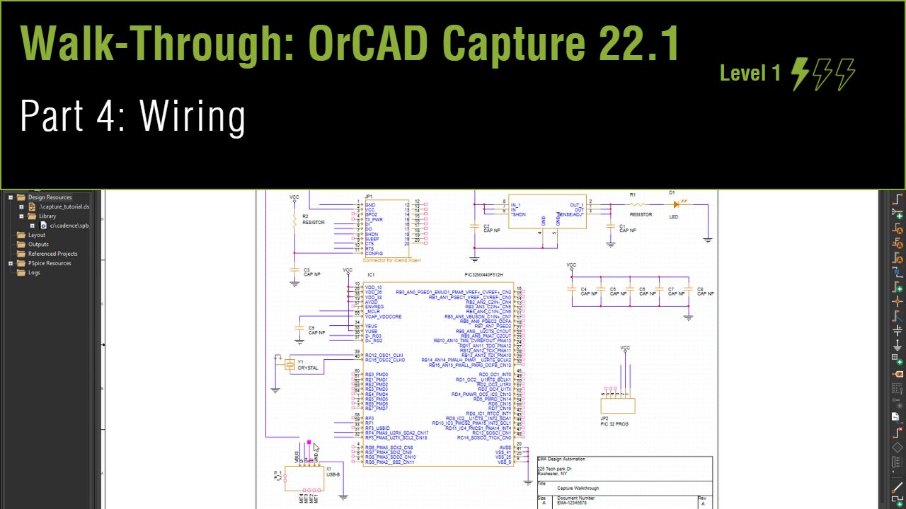
Lesson 4: Wiring
This walk-through demonstrates several techniques for connecting components in OrCAD Capture version 22.1 (2022). After you complete this topic, you will be able to:
- Connect components to wires
- Select and move groups of wired components
- Connect a bus to components and nets
To follow along, continue with the design from the last topic or use the provided design files. If the design files were not downloaded in the beginning of the Capture Walk-Through, the design files for this lesson can be found under the Materials tab.
 Open in New Window
Placing Wires
Step 1: Select Place > Wire from the menu or the W button on the toolbar.
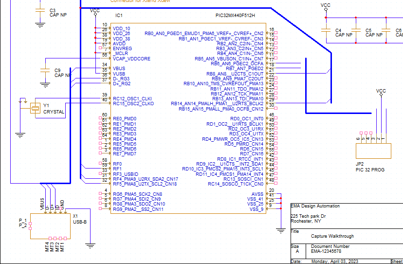
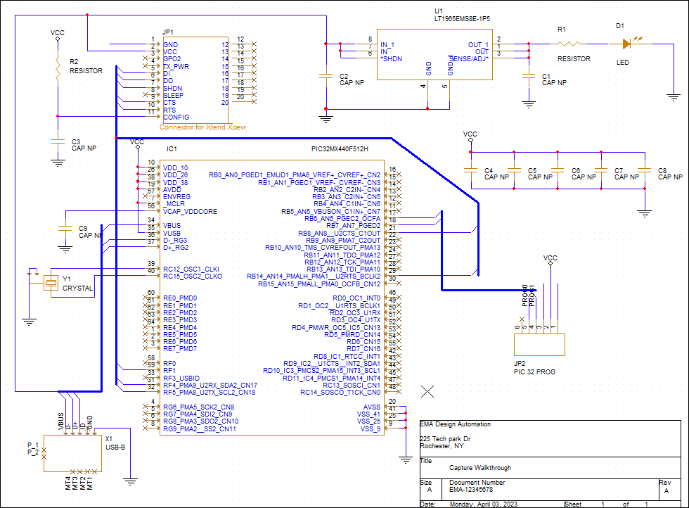
Step 2: Click each connection to add a wire and click again to finish. Wire the schematic as per the provided Capture Tutorial.pdf.
Note: Click and drag to adjust components as needed for optimal spacing. To copy and paste wires, use CTRL+C and CTRL+V on the keyboard.
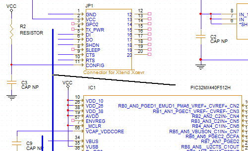
Step 3: Add a short wire to the pins that will be connected to buses or net aliases:
- For component JP1: pins 1, 5 ,6, 7, 9, and 10
- For component JP2: pins 1 and 3
- For component IC1: pins 7, 31, 32, and 59
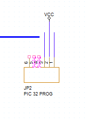
Note: To repeatedly place a wire use F4 on the keyboard. Pins 4 and 5 of JP2 will be automatically connected to a bus, so do not add short wires to those pins.
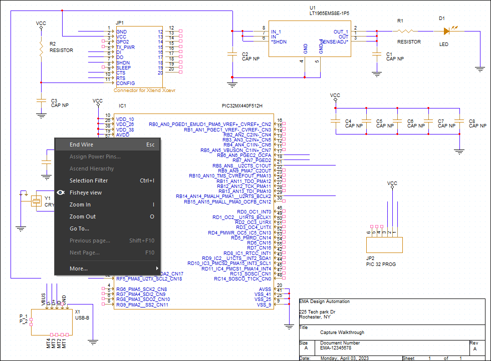
Step 4: When finished, right-click and select End Wire.
Note: Selecting End Wire will place the wire outline you have on your cursor. You can easily move sections of your schematic by highlighting and dragging the selection, a component, or a wire.
Placing Buses
Step 5: Select Place > Bus from the menu or press B on the keyboard.
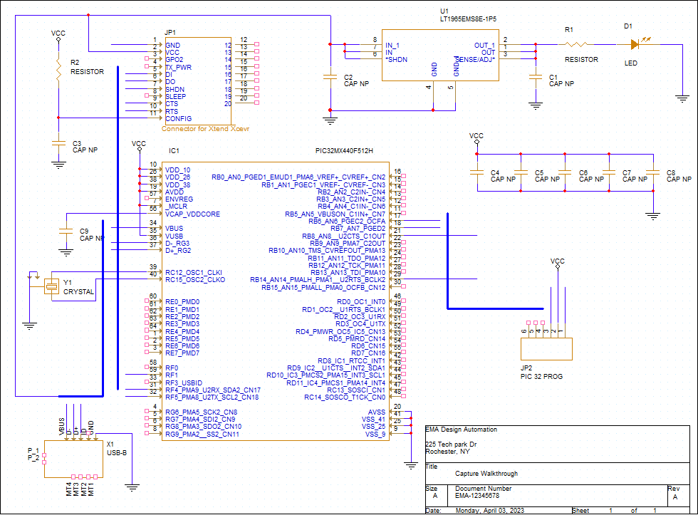
Step 6: Click to place the bus and click again to finish. Add the orthogonal buses as per the provided Capture Tutorial.pdf.
Step 7: With bus mode still activated, hold Shift and start drawing the section of the first bus between IC1 and JP2. A bus can now be added diagonally.
Note: In your own designs, you can choose whether to use diagonal or orthogonal buses. Diagonal buses are often used to improve schematic readability as they may be easier to discern from standard wires placed at 90-degrees.
Step 8: Click to draw the last bus as per Capture Tutorial.pdf. Press Escape on the keyboard when finished.
Placing Bus Entries Manually
Step 9: Select Place > Bus Entry from the menu.
Step 10: Click to place the bus entry for
- Component JP1: Pins 5, 6, 7, 9, and 10
- Component IC1: Pins 21, 29, 31, 32, 34, 36, 37, and 59
- Component X1: All pins
Note: Use R on the keyboard to rotate the bus entry.
Placing Bus Entries Automatically
Step 11: Select Place > Auto Wire > Connect to Bus from the menu.
Step 12: Select pin 5, then pin 4 of JP2.
Step 13: Select the bus to connect the pins.
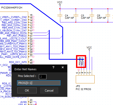
Step 14: The Enter Net Names window will appear. Enter the name PROG[0-1] and click OK.
Note: If the bus has sequential nets add the name, a bracket, and the set of numbers. This will add the net names to all the selected nets. For better visibility, click and drag net names.
Placing No Connects
Step 15: Select Place > No Connect from the menu or press X on the keyboard.
Step 16: Click to place no connects on all unused pins. Right-click and select End Mode when finished.
Note: At this point in the walk-through, pins with only short wires connected are not unused. These connections will be completed in the next lesson.