PCB Walk-through 9: Manufacturing Export
This walk-through demonstrates how to generate manufacturing export files. After you complete this topic, you will be able to:
- Generate IPC-2581 output
- Generate Gerber Artwork files
- Generate NC Drill file
To follow along, continue working with the design completed in PCB Walkthrough 8 or open the provided board file in the folder directory, PCB Walkthrough 9_Manufacturing Export.
If the design files were not downloaded in the beginning of the walk-through, they can be accessed through the Materials tab above.
 Open in New Window
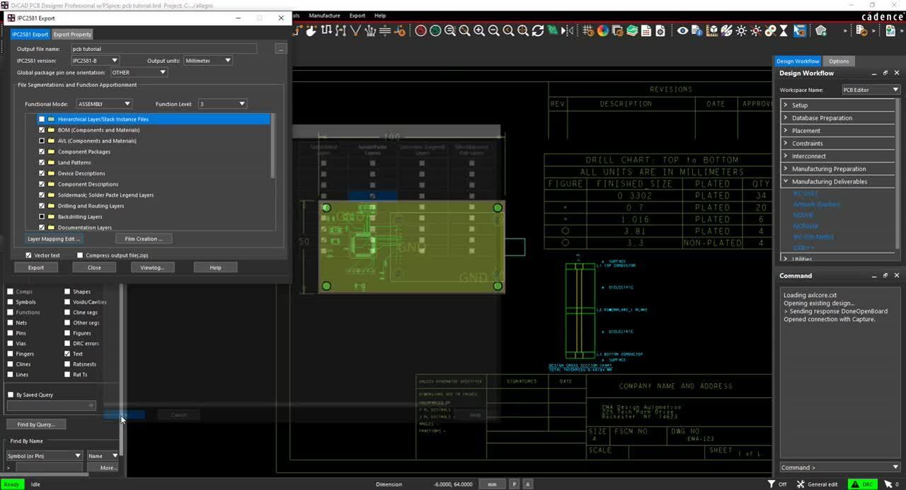
- In the Design Workflow, select Manufacturing Deliverables > IPC-2581.
Note: All layers have been generated during the setup of Gerber films.
- Select Layer Mapping Edit.
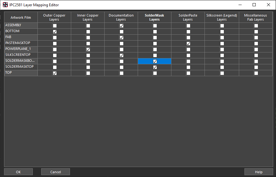
- Select ASSEMBLY, FAB, and SILKSCREENTOP as Documentation Layers.
- Select SOLDERMASKBOTTOM AND SOLDERMASKTOP as SolderMask Layers.
- Select PASTEMASKTOP as a Solderpaste Layer.
- Click OK.
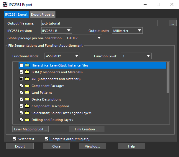
- Select Compress output file and Export.
- In the Design Workflow, select Manufacturing Deliverables > Artwork (Gerber).
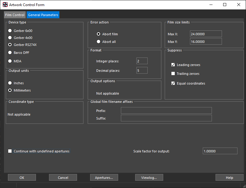
- Select the General Parameters tab and select Gerber RS274X.
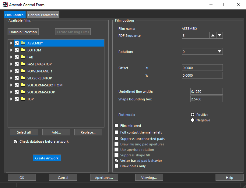
- Select the Film Control tab. Select All and Create Artwork.
- Click OK.
- In the Design Workflow, select Manufacturing Deliverables > NC Drill.
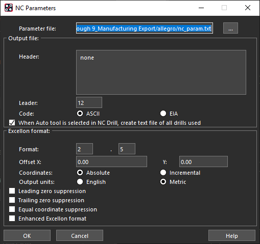
- Select Parameters. Use the defaults and click OK.
- Select Drill.
- Close the window.