Capture Walk-through 2: Creating Parts
This walk-through demonstrates several ways you can create and add parts to a Capture library. After you complete this topic, you will be able to:
- Copy library parts and paste them into a new design library
- Rename and edit a library part
- Create a new part and add it to your design library
To follow the instructions presented in this tutorial, continue using the design you completed in Capture Walk-through 1 or use the included design file, CAPTURE TUTORIAL 2_CREATING PARTS.DSN under the ‘materials’ tab.
 Open in New Window
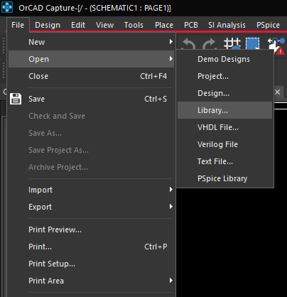
- Select File > Open > Library from the menu.
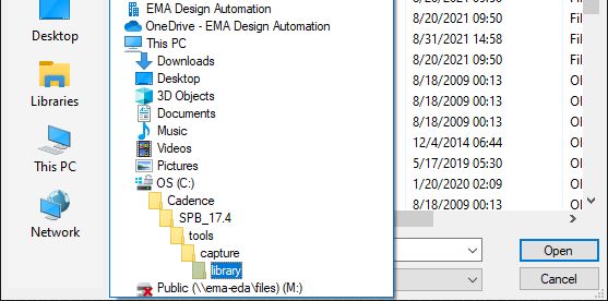
- Use the following path to access the default libraries provided in Capture:
C:\Cadence\SPB_17.4\tools\capture\library
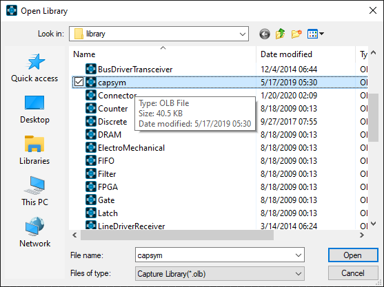
- Open the CAPSYM.OLB library.
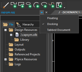
Note: Click on the arrow located in the right of the library, to change the view of the window: docked, floating or a tabbed document.
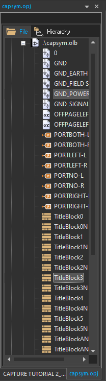
- Select Ground_Power and Titleblock3 in the capsym.olb library.
Note: To select multiple items hold down the CTRL on the keyboard and select the desired items.
- Use CTRL+C on the keyboard to copy.
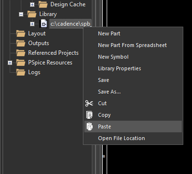
- In the Capture Tutorial project hierarchy, right click on the Capture Tutorial library and select Paste.
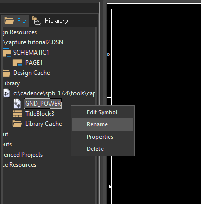
- Right click on GND_POWER and select Rename. Rename the part to GND.
- Right click on Titleblock3 and select Rename. Rename the part to TitleBlock.
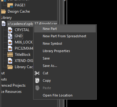
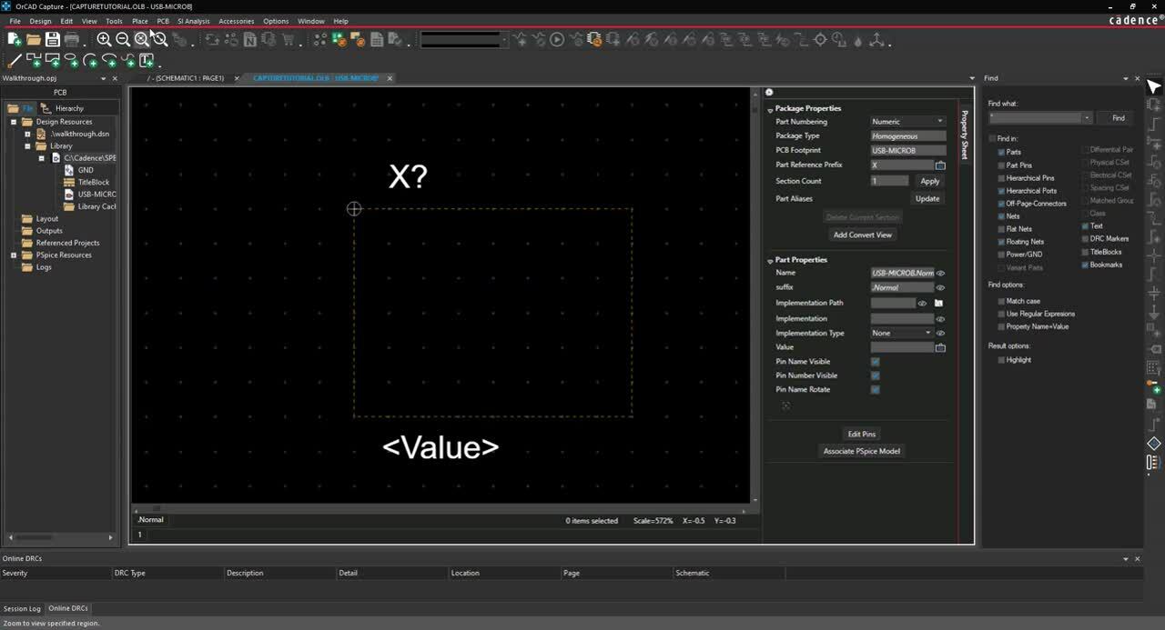
- Right click on the Capture Tutorial library and select New Part.
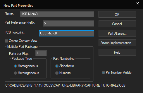
- Enter the following information:
- Name: USB-MicroB
- Part Reference Prefix: X
- PCB Footprint: USB-MicroB
Note: Use TAB on the keyboard to quickly go to the next field.
- Click OK.
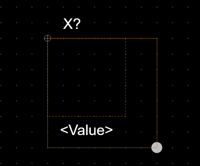
- Click the boundary part and drag the vertex to resize the boundary box.
- Select Place > Rectangle from the menu.
- Click and drag to draw the rectangle.
- Right click and select End Mode (ESC).
- Select Place > Pin from the menu.
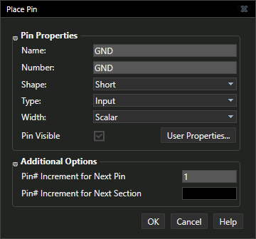
- Enter the pin properties below in the Place Pin dialog window:
- Name: GND
- Number: GND
- Shape: Short
- Type: Input
- Click OK.
- Click a location on the part boundary to place the pin.
- Use Shift+G on the keyboard to re-open the Place Pin window. Enter the values for the next pin.
- Continue placing pins using the pin properties below.
| Name | Number | Shape | Type |
| USBID | ID | Short | Input |
| D+ | D+ | Short | Input |
| D- | D- | Short | Input |
| VBUS | VBUS | Short | Input |
| MT1 | MT1 | Zero Length | Bi-Directional |
| MT2 | MT2 | Zero Length | Bi-Directional |
| MT3 | MT3 | Zero Length | Bi-Directional |
| MT4 | MT4 | Zero Length | Bi-Directional |
| P_1 | P_1 | Zero Length | Bi-Directional |
| P_2 | P_2 | Zero Length | Bi-Directional |
Note: When the pin ends in a number the next pin placed will be sequential. You can continue to click and place MT1 to MT4 and P_1 to P_2 without editing properties between pins.
- Right Click and select End Mode when finished (ESC).
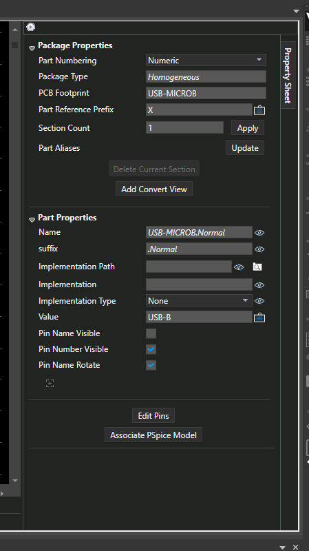
- In the Property Sheet, de-select the Pin Name Visible check box.
- Select the Value text. Right click and select Rotate.
- Click and drag the text to a new location.
- Double click the text.
- Change the value to USB-B and Enter.
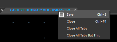
- Right click the part tab. Select Save and Close.
Note: A part can be viewed and edited by double clicking the name in the library. In the Property Sheet, select Edit Pins to edit all the pins in the part.