Capture Walk-through 4: Wiring
This walk-through demonstrates several techniques for connecting components in OrCAD Capture version 17.4-2021. After you complete this topic, you will be able to:
- Connect components to wires
- Select and move groups of wired components
- Connect a bus to components and nets
To follow along with this tutorial, continue with the design you completed for Capture Walk-through 3 or use the included design file, CAPTURE TUTORIAL 4_WIRING.DSN under ‘materials’ tab.
 Open in New Window
Reference the provided Smart PDF, capture tutorial.pdf, to assist with wiring.
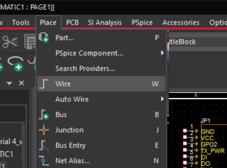
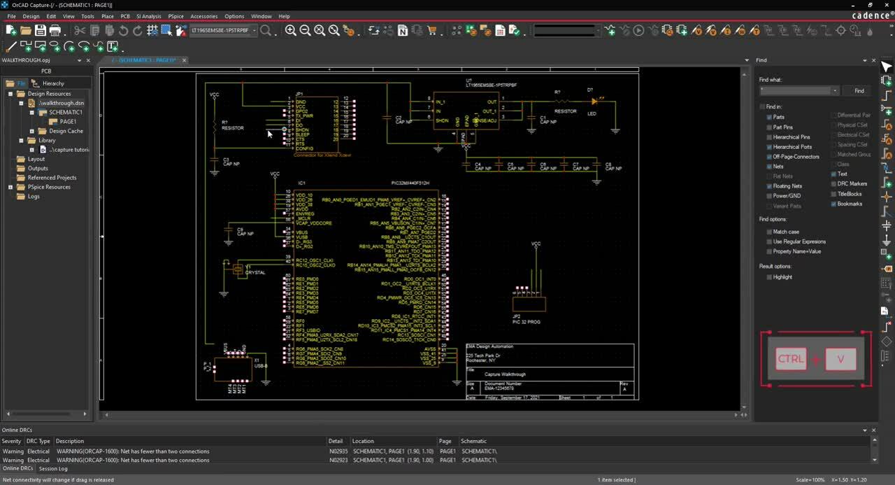
- Select Place > Wire (W) from the menu.
- Click each connection to add a wire.
- Wire the schematic according to the provided Capture Tutorial.PDF.
Note: To copy and paste wires, use CTRL+C and CTRL+V on the keyboard. To repeatedly place a wire use F4 on the keyboard. Add a short wire to the pins that will be connected to buses or net aliases, for components JP1 (pins 1, 5 ,6, 7, 9, 10), JP2( pins 1 and 3) and IC1 (pins 7, 31, 32, and 59)
- Right click and select End Mode (ESC).
Note: Selecting “end wire” will place the wire outline you have on your cursor. You can easily move sections of your schematic by highlighting and dragging the selection, a component or a wire.
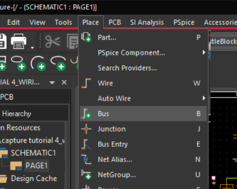
- Select Place > Bus (B) from the menu.
- Click to place the bus.
Note: To add a bus at an angle hold down Shift on the keyboard.
- Right click and select End Mode (ESC).
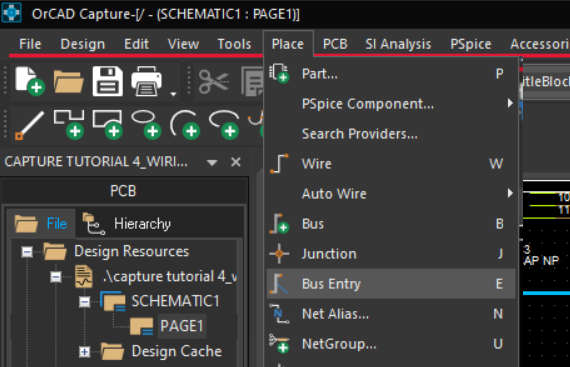
- Select Place > Bus Entry (E) from the menu.
- Click to place the bus entry for JP1 (pins 5, 6, 7, 9 and 10 ) and IC1 (pins 31, 32, and 59 )to connect the wires and bus.
Note: Use R on the keyboard to rotate the bus entry.
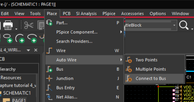
- Select Place > Autowire > Connect to Bus from the menu.
- Select the pin you want to connect then select the bus.
- Type the name of the net and click OK.
Note: If the bus has sequential nets add the name, a bracket, and the set of numbers. This will add the net names to all the selected nets.
- Finish wiring the buses according to the provided Capture Tutorial.PDF.
- Select Place > No Connect from the menu (X).
- Click on the pins that are not connected according to Capture Tutorial.PDF.
- Right click and select End Mode (ESC).