Capture Walk-through 9: Design Rule Check
A Design Rule Check (DRC) checks your design for violations and identifies problem-areas with schematic error markers. The DRC report lists all objects checked and the rule violations detected.
This walk-through demonstrates how to view and correct design rule violations. After you complete this topic, you will be able to:
- Configure and run a design rule check (DRC)
- Correct violations
To follow along with this tutorial, continue with your design from Capture Walk-through 8 or use the included design file, CAPTURE TUTORIAL 9_DRC.DSN under the ‘materials’ tab.
 Open in New Window
- Expand the Online DRC window.
Note: This New feature in 17.4 reports real-time warning violations. Enabling you to correct errors while you design. Like the other windows in the Capture workspace, the Online DRC window can be either floating or docked. Cross probe between the violation and the schematic by double clicking a line item.
- In the project hierarchy, select the design file.
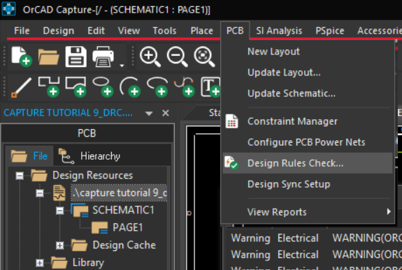
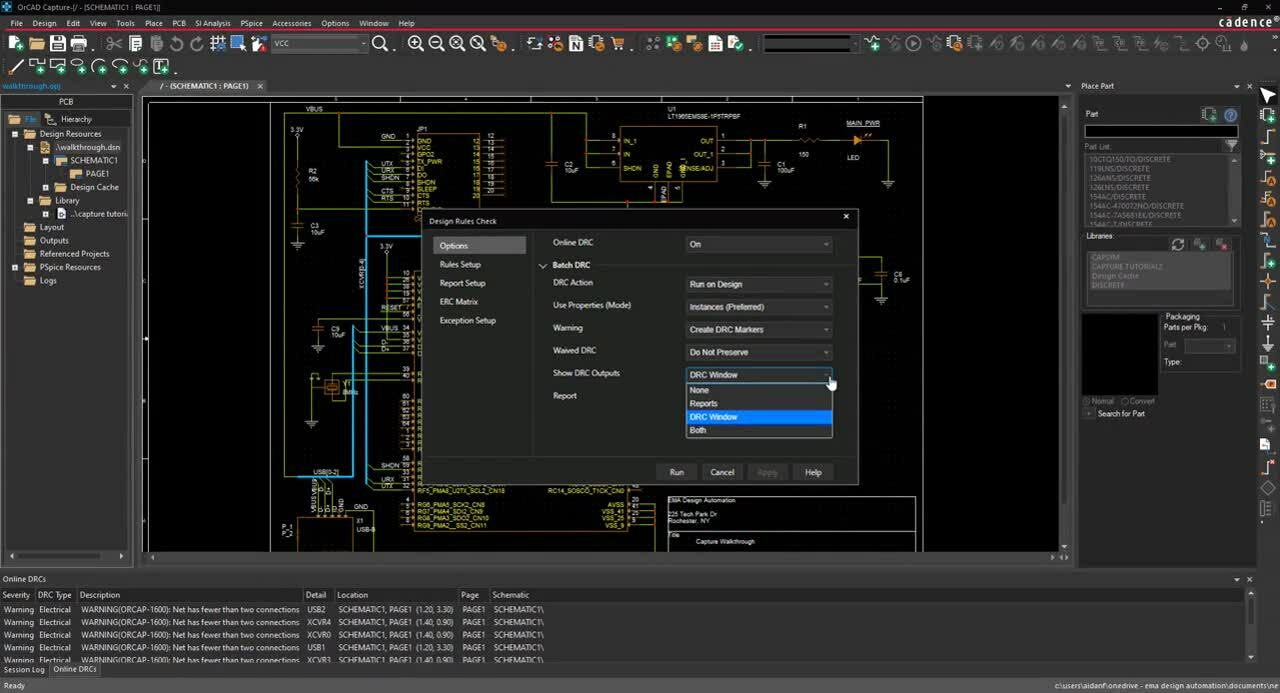
- Select PCB > Design Rule Check from the menu.
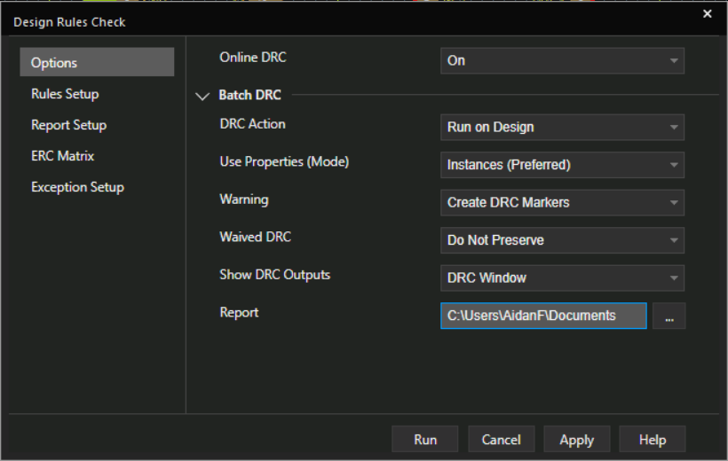
- In the Options tab, for DRC Action set Run on Design
- For Use Properties (Mode) set Instances (Preferred)
Note: If you have a hierarchical design, select Occurrences for this setting.
- For Warning set Create DRC Markers.
- For Show DRC Output set DRC Window.
- Browse to the location to save the report.
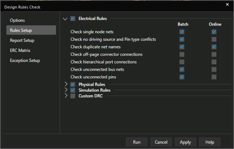
- Select the Rule Setup tab. Leave the defaults.
Note: Here you can select which electrical and physical rules to check in the design. Custom rules can also be assigned.
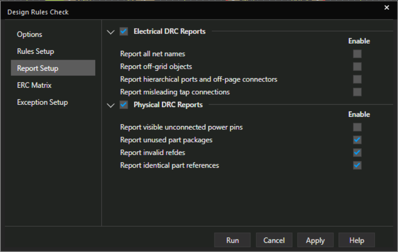
- Select the Report Setup tab. Leave the defaults.
Note: Here you can select which electrical and physical items are included in the report.
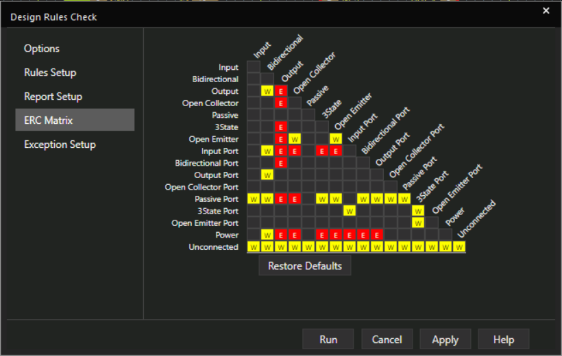
- Select the ERC Matrix tab. Leave the defaults.
Note: This matrix is used to test connections between pins, hierarchical blocks, and hierarchical ports.
The ERC Matrix flags invalid pin-to-pin function connections found within the design. The Matrix shows all possible pin-to-pin combinations. Define a pin combination by toggling between valid (empty) or invalid (flagged with an error or warning).
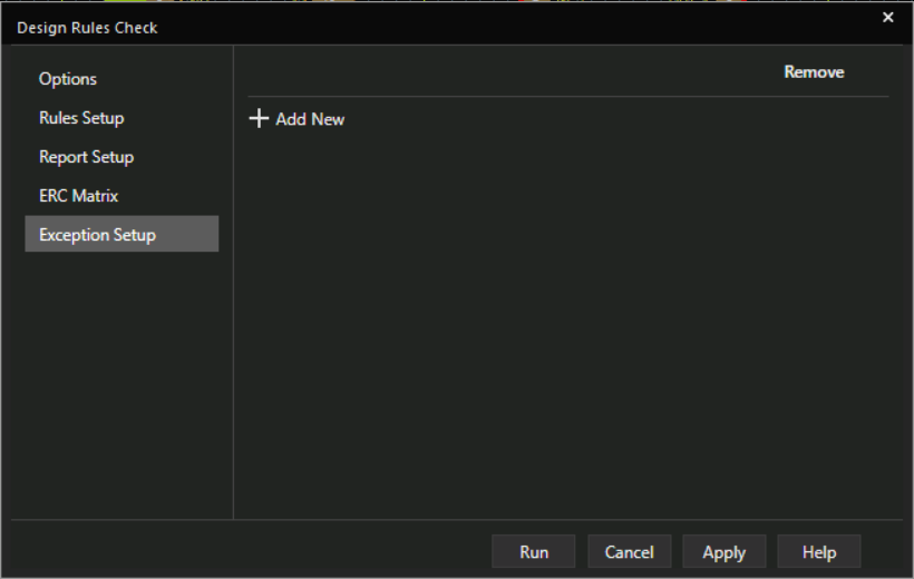
- Select the Exception Setup tab.
Note: Here you can define rules you want excluded from the DRC by selecting the Add New button.
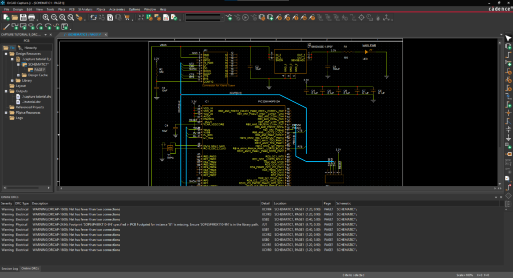
- Select Run to generate the DRC Report.
- View the warnings in the DRC Window.
Note: Double click on a warning to be brought to the location in the schematic.
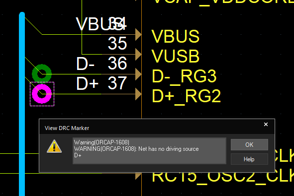
- In the schematic, double click on a marker to see more information on the warning.
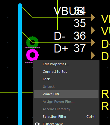
Note: To waive a DRC, right click on a marker and select Waive DRC.
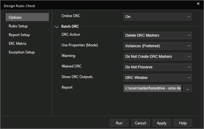
To remove all markers, Select PCB > Design Rule Check from the menu. In the Options tab, select Delete DRC Markers for Action or Do not create DRC Markers for Warning. Select Run to update the schematic.
