Lesson 3: Creating Parts
This walk-through demonstrates several ways you can create and add parts to a Capture library. After you coWhile OrCAD X Capture contains default libraries of common schematic symbols as well as integrated access to industry-leading sources for component models, such as Ultra Librarian, sometimes parts will need to be created manually. This walk-through demonstrates part creation in OrCAD X Capture 25.1. After you complete this topic, you will be able to:
- Create a new part
- Add a new part to your design library
- Add a library to your Capture project
- Remove a library from your Capture project
To follow along, continue with the design from the last topic or download the provided design under the Materials tab.
 Open in New Window
Creating Parts in OrCAD X Capture 25.1
Step 1: Right-click the CAPTURETUTORIAL.OLB library and select New Part.
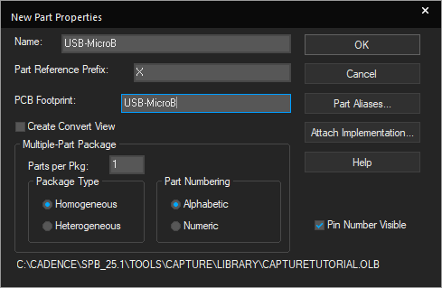
Step 2: Enter the following information:
- Name: USB-MicroB
- Part Reference Prefix: X
- PCB Footprint: USB-MicroB
Note: Use TAB on the keyboard to quickly go to the next field.
Step 3: Click OK. The Part Editor tab opens.
Step 4: Click the boundary to display vertices.
Step 5: Click and drag the lower-right vertex to resize the boundary box to seven-by-seven units.
Step 6: Select Place > Rectangle from the menu.
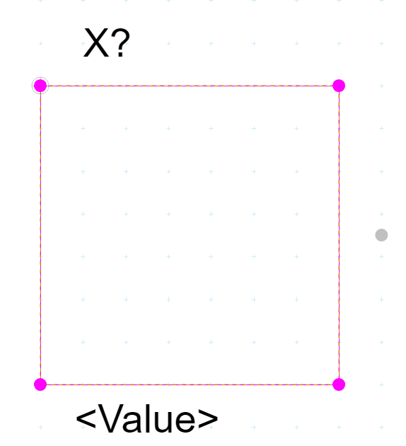
Step 7: Click to start drawing the rectangle and click again to finish. Right-click and select End Mode.
Step 8: Select Place > Pin from the menu.
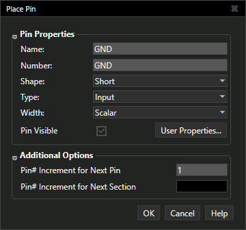
Step 9: Define the pin properties as follows and click OK to place.
- Name: GND
- Number: GND
- Shape: Short
- Type: Input
Step 10: Click a location on the part boundary to place the pin.
Step 11: Press Shift-G on the keyboard to re-open the Place Pin window.
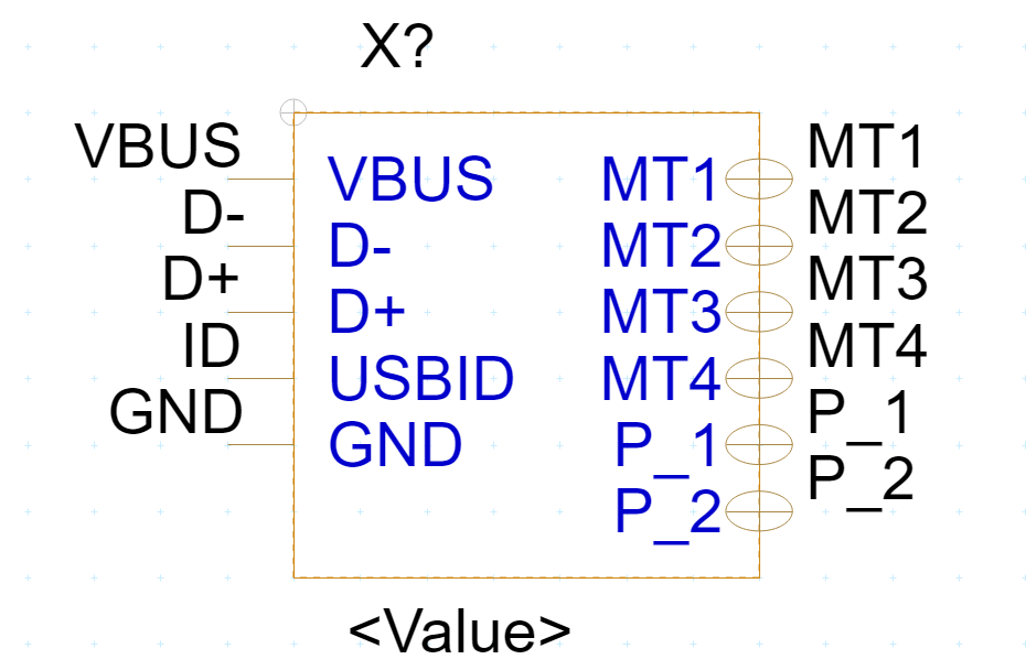
Step 12: Enter the pin values and place the pins using the properties below.
| Name | Number | Shape | Type |
| USBID | ID | Short | Input |
| D+ | D+ | Short | Input |
| D- | D- | Short | Input |
| VBUS | VBUS | Short | Input |
| MT1 | MT1 | Zero Length | Bi-Directional |
| MT2 | MT2 | Zero Length | Bi-Directional |
| MT3 | MT3 | Zero Length | Bi-Directional |
| MT4 | MT4 | Zero Length | Bi-Directional |
| P_1 | P_1 | Zero Length | Bi-Directional |
| P_2 | P_2 | Zero Length | Bi-Directional |
Note: When the pin ends in a number the next pin placed will be sequential. You can continue to click and place MT1 to MT4 and P_1 to P_2 without editing properties between pins.
Step 13:Right-click and select End Mode when finished.
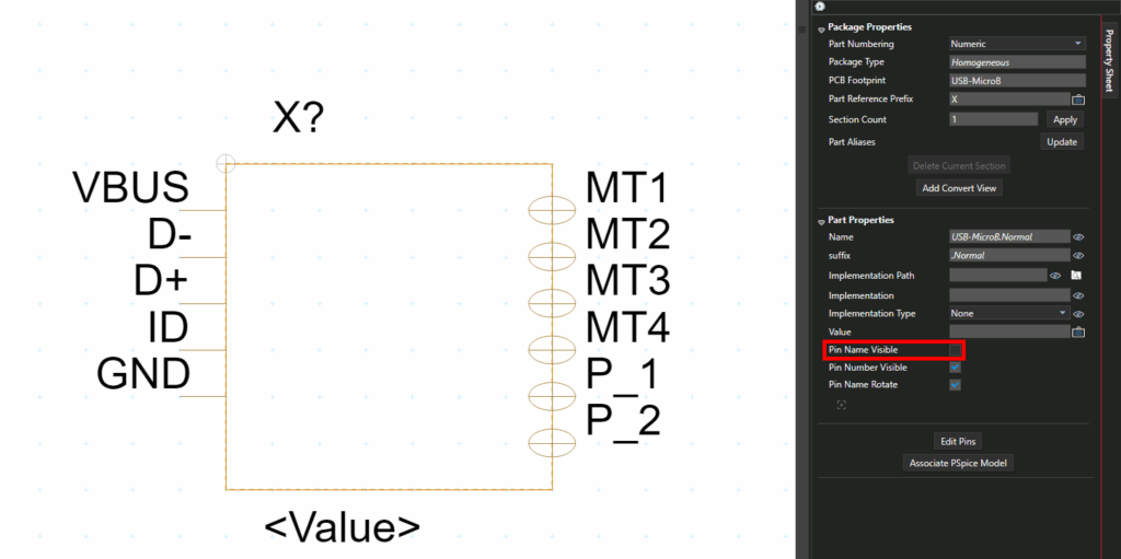
Step 14: In the property sheet, de-select the Pin Name Visible checkbox.
Step 15: Select the <Value> text. Click and drag to move the text to a new location.
Note: Right-click and select Rotate or press R on the keyboard to rotate the text.
Step 16: Double-click the text. Enter USB-B for the value and press Enter.
Step 17: Click the X to close the part tab or right-click the tab and select Close.
Step 18: A prompt appears to save the changed part. Click Yes to save the part.
Loading an Existing Library
Note: A completed library of the parts required for this design has been included in the materials to accelerate the part creation process. For the purpose of this tutorial, the following steps will show how to add the completed library to your project.
Step 19: In the project hierarchy, right-click Library and select Add File.
Step 20: The file browser opens to the default library folder. Select CAPTURE_TUTORIAL_LIB.OLB and click Open.
Step 21: Right-click the first Capture Tutorial library and select Cut.
This completes the part creation lesson. In the next lesson, you will learn multiple methods for placing components in the schematic.
