Lesson 4: Placing Parts
This walk-through demonstrates several techniques you can use to search for parts and place them on your schematic in OrCAD X Capture 25.1. OrCAD X Capture includes multiple options for component placement including placing components from:
- Included libraries of commonly used symbols
- Ground
- Power
- Off-Page Connectors
- Title Blocks
- Included libraries of common components
- Included project libraries
- Placing components from databases (Cloud or on-premise)
- Online repositories from industry-leading sources
- Samacsys
- Ultra Librarian
- SnapMagic
After you complete this topic, you will be able to:
- Place a title block
- Place parts from your project library
- Search and place parts from the default Capture libraries
- Place parts from the Component Explorer
- Place schematic elements including ground, and power on a schematic page
To follow along, continue with the design from the last topic or download the provided design under the Materials tab.
 Open in New Window
1. Placing a Title Block
Title blocks contain vital design data including company information, project name, revisions, dates, and more. There are several default title blocks available in OrCAD X Capture as well as the ability to create a custom title block.
Step 1: Select Place > Title Block from the menu.
Step 2: The Place Title Block window opens. Select Add Library.
Step 3: Browse to the default library location, C:\Cadence\SPB_25.1\tools\capture\library. Select capsym.olb and click Open.
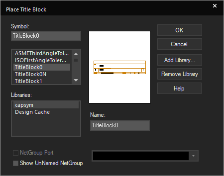
Step 4: Select TitleBlock0 and click OK.
Step 5: Click to place the title block in the lower-right corner of the schematic. Right-click and select End Mode.
2. Placing Parts from the Project Library
Easily access the parts contained in the libraries associated with your project directly in the schematic canvas.
Step 6: Select Place > Part from the menu or press P on the keyboard.
Step 7: Select Capture_Tutorial_Lib from the libraries list.
Step 8: Select PIC32MX440F512H from the part list.
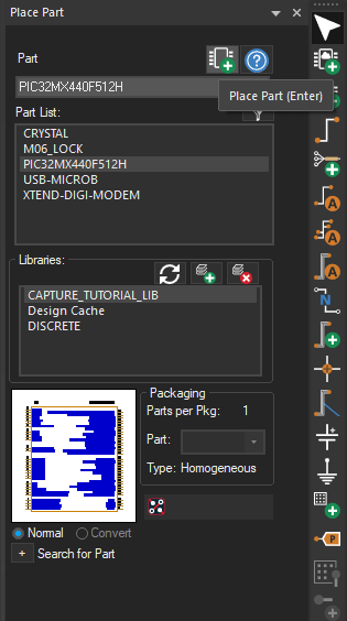
Step 9: Select the Place Part button or double-click the part.
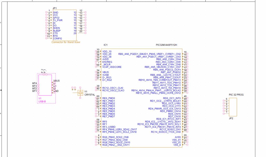
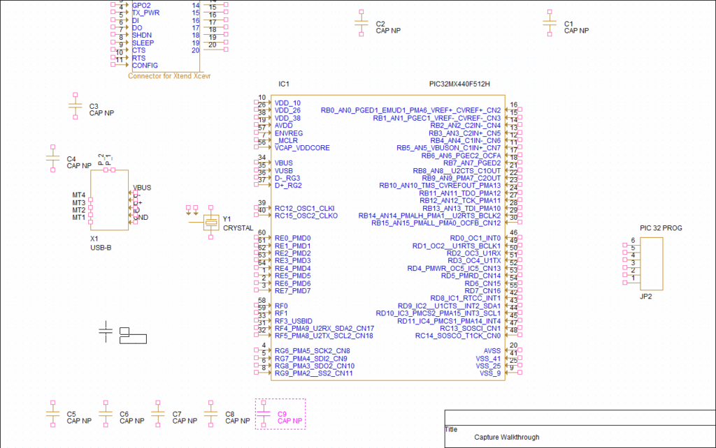
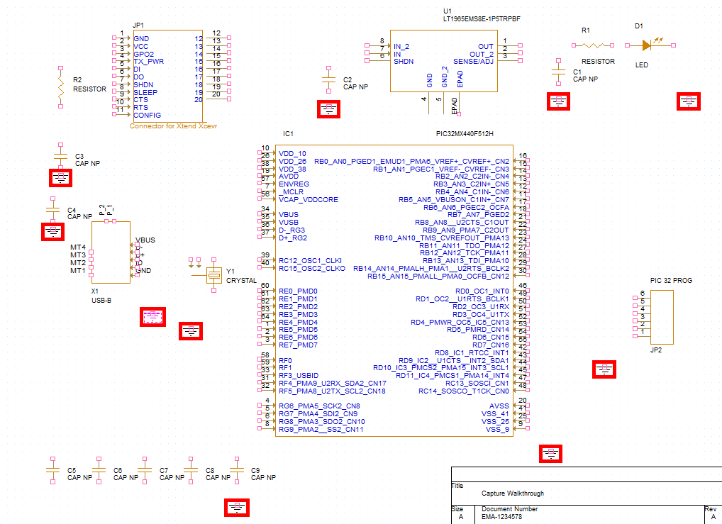
Step 10: Click to place the part on the schematic. Right-click and select End Mode when finished.
Step 11: Repeat steps 8-10 to place JP1, JP2, X1, and Y1 in the schematic, using the table below and the provided Capture Tutorial.pdf as a reference. The table below provides the part numbers and corresponding reference designators.
| Part | Reference Designator in Capture Tutorial.pdf |
| XTEND-DIGI-MODEM | JP1 |
| M06_LOCK | JP2 |
| USB-MICROB | X1 |
| CRYSTAL | Y1 |
Note: To rotate a part during placement, press R on the keyboard, or right-click and select Rotate. This can also be completed once the part is placed.
3. Placing Parts from Included Libraries
Access schematic libraries that are included in the OrCAD X installation for access to common parts as well as vendor-specific parts.
Step 12: Click the plus sign in the Place Part panel to expand Search for Part.
Step 13: Verify that the search path is set to the default Capture library: C:\Cadence\SPB_25.1\tools\capture\library.
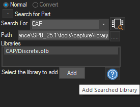
Step 14: Enter CAP into the Search For field and click the Part Search icon.
Step 15: Select the discrete library, labeled as CAP/Discrete.olb.
Step 16: Click Add.
Note: This has added the library and the library can now be searched in the parts window. To add multiple libraries, click the Add Library button. Select all default libraries and Open. This will allow you to search all of the libraries in the Place Part panel. Click the Remove Library button to delete a library from the parts window.
Step 17: Select CAP NP to place a non-polarized capacitor. Double-click the part or click the Place Part icon.
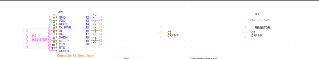
Step 18: Click to place the capacitors according to the provided schematic. Right-click and select End Mode when finished. When completed, make sure nine capacitors have been placed.
Step 19: Enter Resistor into the top search field. Search results are listed automatically.
Step 20: Double-click RESISTOR to place a resistor.
Step 21: Click to place the resistors according to the provided schematic. Right-click and select End Mode when finished. When completed, make sure two resistors have been placed.
Step 22: Enter LED into the top search field.
Step 23: Double-click LED to place an LED.
Step 24: Click to place the LED according to the schematic. Right-click and select End Mode when finished.
4. Placing Parts from Component Explorer
OrCAD X includes integrated access to industry-leading sources. Parts can be placed directly from these sources with access through the Component Explorer. The Component Explorer provides a centralized location which allows you to search and place parts from PSpice libraries, Ultra Librarian, Samacsys, and SnapMagic parts.
Step 25: Select Place > Component from the menu.
Step 26: Select the Ultra Librarian category from the Categories sidebar.
Step 27: Log in by entering your Ultra Librarian credentials. Click OK.
Note: If you do not have an Ultra Librarian account, you can create one here for free.
Step 28: Search for LT1965EM. The unified search results show you the:
- Manufacturer
- Part number
- Description
- Availability of the symbol, footprint, and 3D model
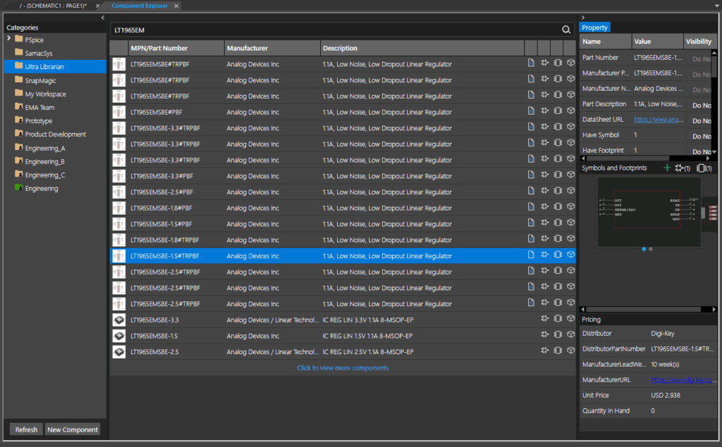
Step 29: Select part LT1965EMS8E-1.5 to view additional information.
Step 30: Right-click and select Place. The part will be downloaded and attached to your cursor.
Note: A part can only be placed in your design when both the symbol and footprint are available.
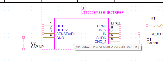
Step 31: Click to place the part in the schematic. Right-click and select End Mode.
Step 32: Parts placed from included providers can be edited to meet your requirements. Select the newly placed part. Right-click and select Edit Part.
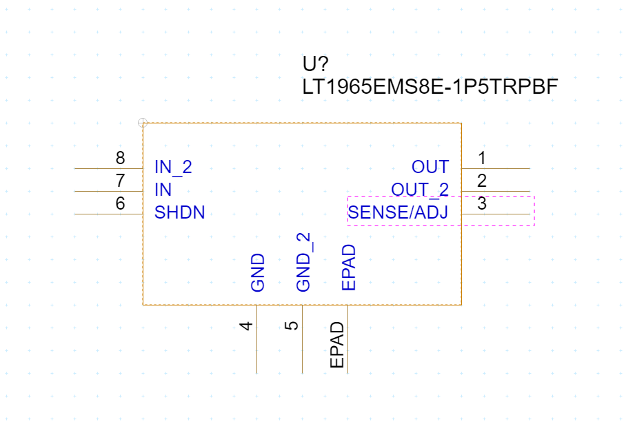
Step 33: Click and drag to rearrange the pins such that:
- The ground pins are on the bottom
- The OUT and SENSE/ADJ pins are on the right
- The IN and SHDN pins are on the left
If you have an extra EPAD or PAD pin, place it on the bottom with the grounds.
Step 34: Click to close the tab. A prompt will appear to update only the current part instance or all instances in the design. Select Update All. Answer Yes to any prompts that follow.
5. Placing Power and Ground
Step 35: Select Place > Ground from the menu.
Step 36: Select GND and click OK.
Step 37: Click to place the ground according to the provided schematic. Right-click and select End Mode when finished. When completed, there should be ten occurrences of the ground symbol.
Step 38: Select Place > Power from the menu.
Step 39: Select capsym from the Libraries list.
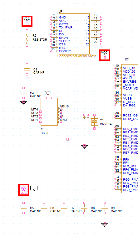
Step 40: Select VCC from the symbol list and click OK.
Step 41: Click to place the power according to the provided schematic. Right-click and select End Mode when finished. When completed, there should be three occurrences of the power symbol.
6. Placing Components from an On-Premise Database (Optional)
If a component database is configured, components can be placed directly from the database into the schematic.
Step 42: Select the Component Explorer tab, then choose CIS ODBC.
Step 43: Select the Query tab in the Explorer window.
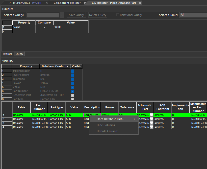
Step 44: In the first row of the query, set the following search criteria:
- Property: Value
- Compare: =
- Value: 56000
Step 45: Press Enter. All 56kΩ resistors in your part database are listed. Review the information including the schematic symbol, PCB footprint, company part status, and more.
Step 46: Right-click a listing in the table and select Place Database Part.
Step 47: From here, you can click and place the component in the schematic as needed. For the purpose of this demonstration, no other components are required, so we will press Escape to end placement mode.
Note: Get more information on using an on-premise CIS database here.
7. Placing Components from a Cloud Database (Optional)
If a cloud-based component database is configured, components can be placed directly from the cloud-based database into the schematic.
Step 48: Select the Component Explorer tab, then choose the desired workspace.
Step 49: The workspace parts are listed. If the list is long, browse through the file structure, enter the name of the desired part, or enter a search parameter such as the value into the Search panel and press Enter.
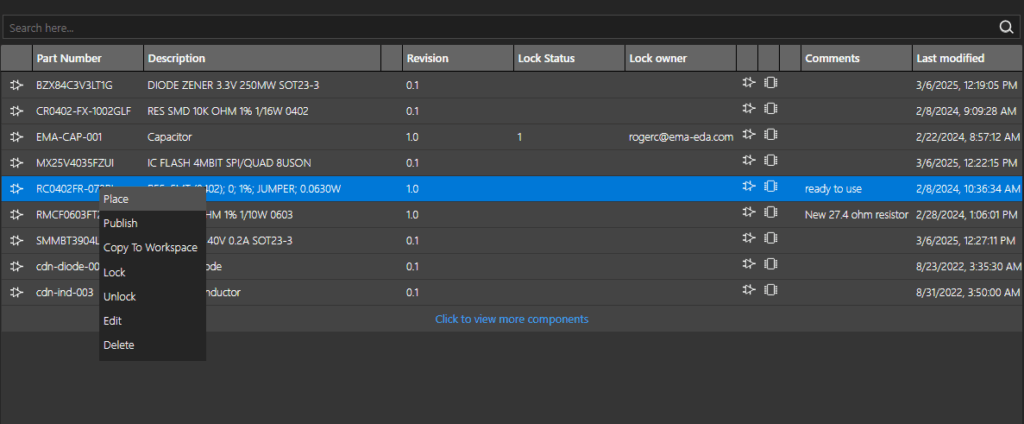
Step 50: Review the returned results and additional component information. Right-click the desired part and select Place.
Note: Parts with a lock status of 1 are currently being edited and should not be placed.
Step 51: From here, you can click and place the component in the schematic as needed. For the purpose of this demonstration, no other components are required, so we will press Escape to end placement mode.
Note: Get more information on using cloud-based libraries here.
This completes the lesson on placing components in the schematic. In the next lesson, you will learn how to establish connections with wiring.
