Lesson 6: Net Aliases
This walk-through demonstrates how to assign and edit net aliases in OrCAD X Capture 25.1. Net aliases are text labels that indicate the name of the net. Net aliases can be used to better communicate design intent and connect schematic wires electrically. After you complete this topic, you will be able to:
- Place net aliases
- Add a new net alias to multiple nets
- Add net aliases to buses
- Verify schematic connections using online Design Rule Checks (DRCs)
To follow along, continue with the design from the last topic or download the provided design under the Materials tab.
 Open in New Window
Placing Net Aliases: Wires
Step 1: Select Place > Net Alias from the menu or press N on the keyboard.
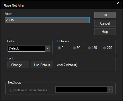
Step 2: Enter VBUS for the net alias and click OK.
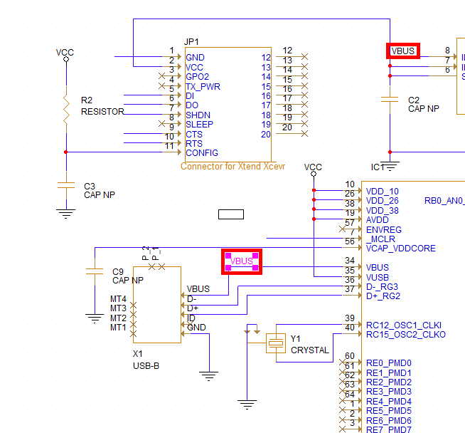
Step 3: By adding the same net alias to multiple nets, you do not need to physically connect them in the schematic. Click to place the alias on:
- The input for the LT1965
- VBUS on the USB-B connector
Note: To rotate, use the R key on the keyboard.
Step 4: Right-click and select Edit Properties or press N on the keyboard to change the alias name.
Step 5: Enter 3.3V for the net alias and click OK.
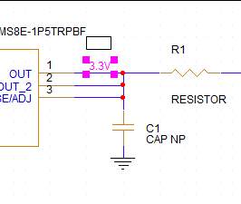
Step 6: Place the alias at the output of the LT1965.
Using the Online DRC to Verify Connections
Online design rule checks can be used to verify schematic connectivity and accuracy in real-time as you design. This allows you to identify and correct errors throughout the schematic creation process. If the online DRC window is not visible, select View > Others > Online DRCs from the menu.

Step 7: View the Online DRC Window. Several of the violations listed in the Online DRCs panel concern a net having fewer than two connections.
Step 8: Double-click a violation with label “Net has fewer than two connections” to view a floating net. This will cross-probe between the violation and the schematic to easily identify design errors.
Step 9: View the violation on the board. The highlighted wire has no connection and no net alias.
Note: When a net alias is placed on multiple wires, those wires are electrically connected.
Correcting Online DRC Errors
Step 10: Select Place > Net Alias from the menu or press N on the keyboard.
Step 11: Enter the appropriate net alias as per Capture Tutorial.pdf and click OK.
Step 12: Click to place on the unconnected wire.
Note: The violation was cleared from the Online DRC window when the net alias was placed, and the connection was completed.
Completing Net Aliases
Step 13: Repeat steps 10-12 for all other displayed net aliases on wires in Capture Tutorial.pdf.
Note: Click and drag to extend wires to make net aliases more readable. If your net has a number at the end of the name, this will be incremented every time you place the net alias. Violations will be cleared as aliases are placed.
Step 14: When finished, right-click and select End Mode.
Placing Net Aliases: Buses
Step 15: Net aliases can similarly be placed on buses. Press N on the keyboard to activate the Net Alias window.
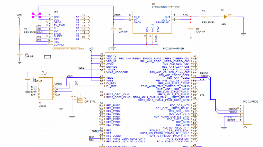
Step 16: Enter PROG[0-1] for the alias name and click OK.
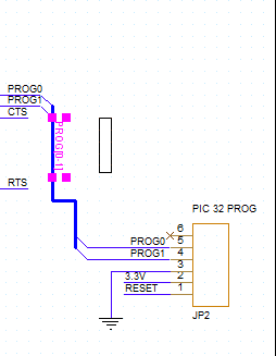
Step 17: Press R to rotate the alias then click to place the alias on the bus that connects IC1 and JP2. Right-click and select End Mode.
Step 18: View the Online DRCs panel again. The violations concerning nets with fewer than two connections have been cleared.
This completes the net alias lesson. In the next lesson, you will learn more about adding part information.
