Lesson 8: Annotating
Reference designators are unique identifiers assigned to each component so you can easily locate, track, and reference them throughout the design, layout, assembly, and documentation process. This walk-through demonstrates how you can update reference designators or annotate your design in OrCAD X Capture 25.1. After you complete the topic, you will be able to:
- Edit reference designator text
- Automatically update schematic annotation
- Understand the differences between unconditional reference and incremental reference updates
To follow along, continue with the design from the last topic or download the provided design under the Materials tab.
 Open in New Window
Annotating A Design: Unconditional Update
Note: This design was automatically annotated when parts were placed. The order in which parts are numbered was determined by the order in which they were placed. For educational purposes, this walk-through will discuss additional options for annotating a design.
Step 1: Select Tools > Annotate from the menu.
Step 2: Under Action, select Unconditional Reference Update.
Note: There are multiple options to annotate a selection or your entire design:
- Select Incremental reference update to annotate only components with question marks in the name.
- Select the Unconditional reference update to re-annotates all components. Use this option if specific names are not required for components.
- Select Reset part references to “?” to reset all reference designators to question marks.
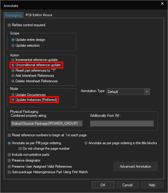
Step 3: Under Mode, select Update Instances.
Note: Update Occurrences is recommended for hierarchical designs. Updating instances will update all parts in the design, even parts on unused pages. In other words, unused parts will factor into the annotations.
Step 4: Click OK to run the annotation.
Step 5: You may be prompted that running annotation will clear the undo/redo cache. Click Yes to proceed.
Step 6: You will be prompted that the tool will annotate then save the design. Click OK to proceed.
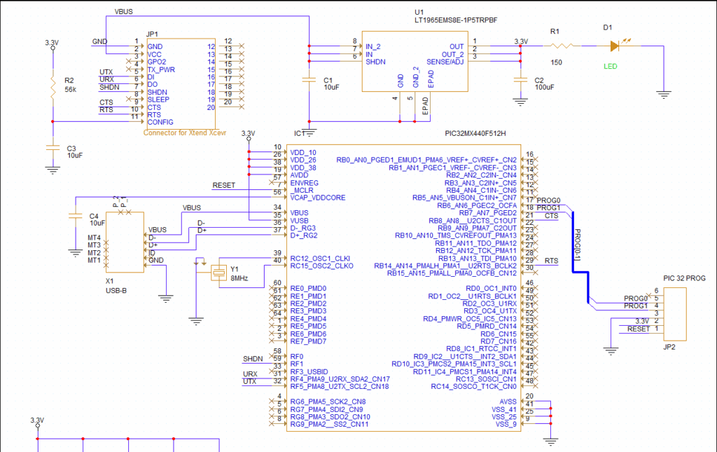
Step 7: View the schematic. All part references have been updated from left to right.
Annotating a Design: Resetting Part References
Step 8: Select Tools > Annotate from the menu.
Step 9: Under Action, select Reset Part References to “?”. This will reset all reference designators to question marks.
Step 10: Click OK to run the annotation. Click Yes and OK when prompted.
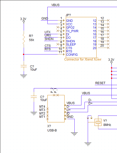
Step 11: View the schematic. The part references have been changed to question marks.
Annotating a Design: Manually Defining Reference Designators
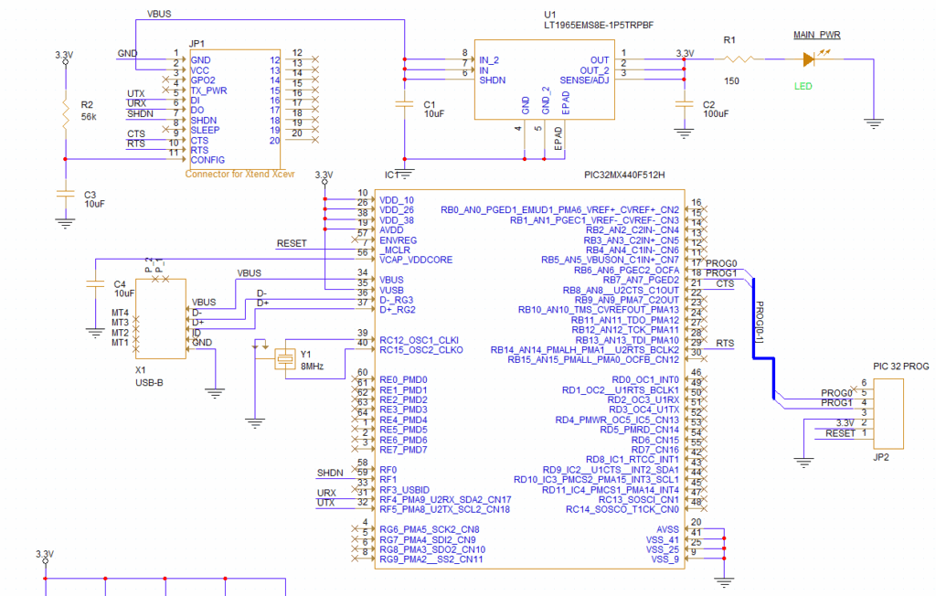
Step 12: Double-click reference designator D? associated with the LED.
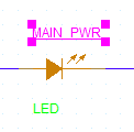
Step 13: Enter MAIN_PWR for the value and click OK. The reference designator is now underlined, indicating that it has been changed by the user.
Annotating a Design: Incremental Update
Step 14: Select Tools > Annotate from the menu.
Step 15: Under Action, select Incremental Reference Update.
Step 16: Click OK to run the annotation. Click Yes and OK when prompted.
Step 17: View the schematic. The MAIN_PWR annotation remains the same, but all other components have been re-annotated.
This concludes the lesson on annotating the schematic. In the next lesson, you will learn how to define differential pairs.
