Lesson 9: Differential Pairs
Differential pairs are groups of two opposing signal nets routed together to create effective noise cancellation and a robust signal path. This walk-through demonstrates how to define differential pairs in the schematic in OrCAD X Capture 25.1. By defining differential pairs, traces will be automatically routed together, and specific rules can be defined for the PCB layout including maximum uncoupled length, primary gap, neck gap, and more. Differential pairs can also be created during the PCB layout. After you complete the topic, you will be able to:
- Define differential pair manually
- Define differential pairs automatically
To follow along, continue with the design from the last topic or use the provided design files. If the design files were not downloaded in the beginning of the Capture Walk-Through, the design files for this lesson can be found under the Materials tab.
 Open in New Window
Creating Differential Pairs Manually
Step 1: Select capture_tutorial.dsn in the project hierarchy.
Step 2: Select Tools > Create Differential Pair from the menu.
Step 3: Select net D+ from the net list.
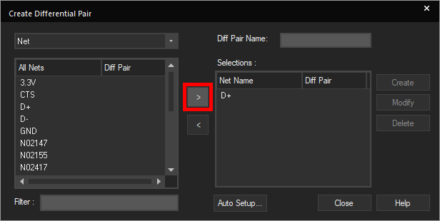
Step 4: Select the > arrow to move the net to the Selections list.
Step 5: Select net D- from the list.
Step 6: Select the > arrow to move the net.
Step 7: Enter DPD into the Diff Pair Name field.
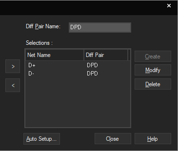
Step 8: Click Create to create the differential pair.
Note: By defining a differential pair, the nets of the differential pair will be routed together in the PCB.
Creating Differential Pairs Automatically
Note: In this walk-through, we will delete the differential pair only to show the automatic process of creating a differential pair. For typical designs, use either manual or automatic creation.
Step 9: Select Delete to clear the differential pair definition.
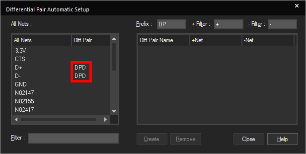
Step 10: Select Auto Setup to open the Automatic Setup window.
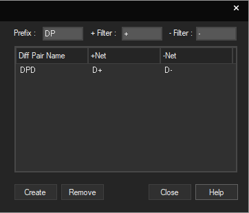
Step 11: Automatic setup automatically identifies nets with the defined suffixes and assigns differential pairs based on the defined prefix, positive suffix filter and negative suffix filter. Enter DP into the Prefix field.
Step 12: Enter + into the + Filter field.
Step 13: Enter – into the – Filter field.
Note: Use the TAB key to quickly jump to the next field.
Step 14: Click the Diff Pair window to generate the differential pair.
Step 15: Click Create to create the differential pair.
Step 16: Click Close to close the Automatic Setup window.
Step 17: Click Close to close the Create Differential Pair window.
This completes the lesson on differential pair creation. In the next lesson, you will learn how to configure and perform a design rule check of the schematic.
