When creating a PCB design, you need a CAD tool meets your design needs by providing real-time feedback and modifications to quickly produce the desired layout. Real-time shapes in OrCAD X Presto provide immediate visualization of the dynamic shapes in your designs. In OrCAD X Presto, all shape attributes have been moved to the properties pane allowing you to easily alter shape properties and shape fills in real-time.
This quick how-to will provide step-by-step instructions on how to work with dynamic real-time shapes in OrCAD X Presto.
How-To Video
 Open in New Window
Real-Time Shapes in OrCAD X Presto
Note: Dynamic shapes or real-time shapes in OrCAD X Presto automatically heal and plow as required when routed through.
Step 1: Open a design in OrCAD X Presto.
Step 2: With a copper shape already placed in the design, select the Add Connect button on the toolbar.
Step 3: Click a connection to begin routing. Click to place the trace on the PCB through the copper shape then click to complete the connection.
Step 4: View the routed trace. The copper shape has been automatically moved away from the routed net based on the constraints assigned in the constraint manager.
Note: Routing or sliding an etch through a shape will automatically clear the shape from the routed net based on the constraint rules.
Step 5: Select Slide from the toolbar.
Step 6: Click a trace segment to activate sliding.
Step 7: Move the cursor to the desired location then click to place the trace. The copper shape where the trace was previously located has automatically healed.
Clearing a Shape Island
Note: While routing or editing a design, an undesirable shape island, or an area of the shape that isn’t electrically connected to its assigned net, may be created. These need to be addressed prior to fabrication and can be easily found with Design Rule Checks in OrCAD X Presto.
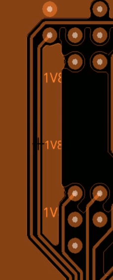
Step 8: Click to select another trace on the PCB. Slide the trace to create a shape island.
Step 9: Select the Refresh button for Out of Date Shapes in the Properties panel to refresh shape/net definitions.
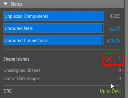
Note: The Shape Islands count in the Properties panel is increased.
Step 10: Select the hyperlink for Shape Islands to view the list of all islands in the design.
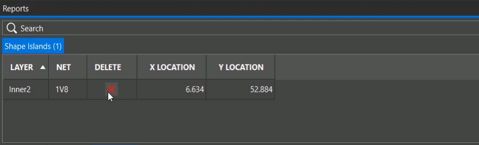
Step 11: The search panel activates at the bottom of the PCB canvas displaying all the reported shape islands for the design. Click the X under Delete to delete the island.
Adjusting a Chamfered Shape
Note: Most copper shapes not on the edge of a board will have chamfered corners. Such shapes can be adjusted while preserving the chamfered corners in OrCAD X Presto.
Step 12: Select a chamfered shape.
Step 13: Several adjustment points are visible. Click and drag a point on an edge to adjust the shape while preserving the corner chamfers.
Note: Press T on the keyboard to cancel corner preservation.
Adjusting Shape Priority
Note: For overlapping shapes with different nets, priority can be adjusted in the Properties panel.
Step 14: Select a shape that overlaps another shape on a different net in the Presto canvas.
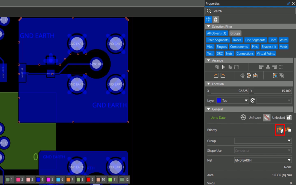
Step 15: In the Properties panel, select Raise Priority to move the shape forward.
Step 16: Select Lower Priority to move the shape back or forward.
Other Shape Adjustments
Note: Shape properties can be modified with easy access in the Properties panel.
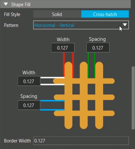
Step 17: With the shape still selected, in the Properties panel, scroll down to the Shape Fill subpanel and select Cross-Hatch for the Fill Style.
Step 18: Select the desired pattern from the Pattern drop-down. Patterns include:
- Vertical
- Horizontal
- Diagonal Positive
- Diagonal Negative
- Diagonal Both
- Horizontal-Vertical
- Custom
Note: A visual graphic displays the selected pattern as well as modifiable fields for easy adjustment.
Step 19: Select Solid for the Fill Style to return to the solid mode.
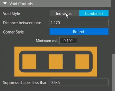
Step 20: Under Void Control, select Combined to combine the voids for close pins.
Note: A preview of the combined voids is shown in the Void Controls subpanel.
Step 21: Under Void Control, select Individual to separate the voids for close pins by copper.
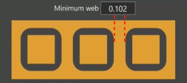
Note: Define the minimum web size, or the minimum thickness of the separating copper, in the Properties panel.
Step 22: Under Thermal Reliefs, select THT Pins to change thermal relief settings for through-hole pins.
Note: Here thermal reliefs can also be configured for:
- All pins
- SMD Pins
- Vias
Step 23: Change the thermal relief type in the Type dropdown.
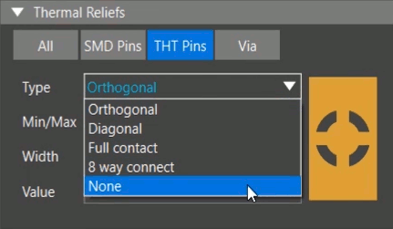
Note: Additional types of thermal reliefs include:
- Orthogonal
- Diagonal
- Full Contact
- 8 Way Connect
- None
The proposed changes will appear live in the design canvas.
Wrap Up & Next Steps
Efficiently modify shapes using centralized access to shape properties, graphical displays, and instant results with real-time shapes in OrCAD X Presto. Test out this feature and more with a free trial of OrCAD X Presto. For more how-tos and step-by-step walk-throughs, visit EMA Academy.
