To accurately tune antennas in your designs, exact values for the shunt capacitors and series inductors must be determined. Manual methods and trial and error approaches to optimize these values can be time-consuming. Efficiently perform antenna matching with AWR Microwave Office to quickly adjust the required capacitor and inductor values, analyze results in real-time, and achieve an optimal antenna configuration.
This quick how-to will provide step-by-step instructions on how to perform antenna matching with AWR Microwave Office.
How-To Video
 Open in New Window
Opening an Antenna Design
Step 1: With AWR Microwave Office open, select Help > Open Example from the menu.
Note: Examples are also accessible by selecting File > Example.
Step 2: In the search bar, type Antenna.
Step 3: Select Log_Spiral_Antenna from the examples and select OK.
Step 4: Select the Projects tab. Under EM Structures, select Spiral.
Step 5: Select Windows > Tile Vertical to configure a full screen configuration for the open windows.
Note: Shortcut keys can be configured to quickly perform commonly used tasks.
Step 6: Select Options > Project Options from the menu. Here you can view the design configuration including the frequency.
Step 7: View the project configuration and click OK.
Analyzing the Antenna

Step 8: Select the Analyze icon from the toolbar. The mesh is generated, analysis is performed on the antenna, and results are displayed including the antenna matching and antenna patterns.
Step 9: Select the 3D Layout icon on the toolbar.
Step 10: View the pattern for the antenna in 3D. Close the window.
Note: To pan and rotate the antenna pattern click and hold the left mouse button, then move the mouse.
Step 11: Expand the Antenna Matching results by double clicking the header bar or selecting the center button in the upper right corner.
Step 12: Select the numerical results displayed on the graph and press Delete on the keyboard.
Step 13: Right-click the graph and select Options.
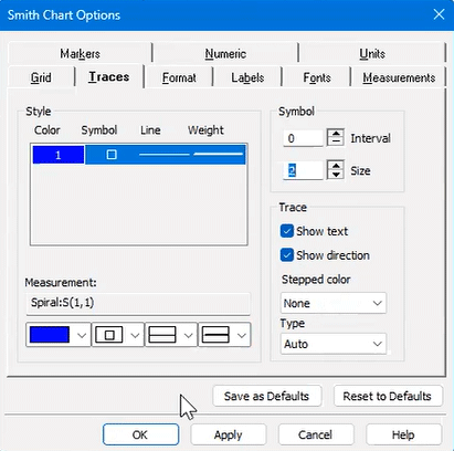
Step 14: Change the Smith Chart options to improve visibility. Select the symbol drop-down, choose the square and adjust the width as desired.
Step 15: Set the Symbol Size to 2 and click OK.
Step 16: Select restore window on top right of the screen to return to the full screen configuration.
Step 17: Close the Antenna Pattern graph.
Creating a Schematic
Step 18: Select the New Schematic icon from the toolbar.
Step 19: Name the schematic Match and click Create.
Step 20: Select the Subcircuit icon on the toolbar.
Step 21: Click OK and click to place in the schematic.
Step 22: Click and drag the text located above the antenna into the center of the schematic symbol.
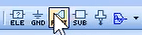
Step 23: Select the Port icon on the toolbar.
Step 24: Click to place the port in the schematic.
Note: Place the port in line with the antenna. The connection is shown with a dotted line and automatically drawn after placement.
Step 25: Select Window> Tile Vertical from the menu to view all three windows simultaneously.
Configuring Settings to Perform Antenna Matching
Step 26: Right-click on the Match Smith Chart and select Add New Measurement.
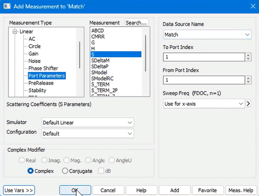
Step 27: Ensure the following parameters are configured:
- Measurement Type: Port Parameters
- Measurement: S
- Data Source Name: Match
- To Port Index: 1
- From Port Index: 1
Step 28: Click OK.
Step 29: Right-click on the Match Smith Chart and select Options.
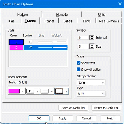
Step 30: In the Smith Chart Options, select trace 2.
Step 31: Under the symbol drop-down select the circle and change the line width to the desired thickness.
Step 32: Leave the Symbol Size as 5 and click OK.
Step 33: Select the Analyze icon on the toolbar.
Step 34: Expand the Match Smith Chart to view the results.
Note: To perform antenna matching, both the impedance and capacitive elements need to be analyzed. To analyze the capacitive aspect, admittance grids can be added to the Smith Chart.
Configuring Admittance
Step 35: Right-click the Smith Chart and select Options.
Step 36: Select the Grid tab and click to select the Admittance Grid.
Step 37: Click OK.
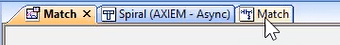
Step 38: Select the Match tab to open the schematic.
Step 39: Select Elements from the left panel and expand Lumped Elements.
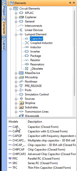
Step 40: Select Capacitor and choose CAP from the expanded list.
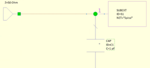
Step 41: Click and drag the capacitor into the schematic and click to place.
Note: With the component selected, right-click to rotate the component. Use CTRL + right-click to flip the component left and right. Use Shift + right-click to flip the component top and bottom.
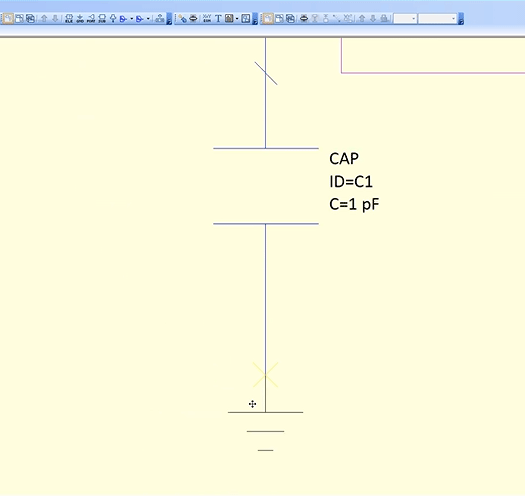
Step 42: Select the GND icon from the toolbar and click to place on the schematic.
Step 43: Double-click the capacitor to edit the Element Options.
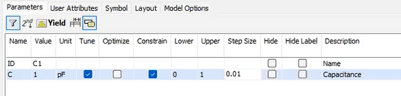
Step 44: Check the box for Tune to make the capacitor value tunable.
Step 45: Check the Constraint box. Set the lower constraint to 0 and the upper constraint to 1 with a Step Size of 0.01. This will tune the capacitor value between 0pF and 1pF using increments of 0.01pF.
Step 46: Click OK. The capacitor value on the schematic is now in blue, indicating this value is tunable.
Step 47: Select the Match Smith Chart tab from the tabbed documents.
Tuning Admittance
Step 48: Select the Analyze icon from the toolbar.
Step 49: Select the Tuning icon from the toolbar.
Step 50: Slide the tuning bar for the capacitor value or use the left arrow key on the keyboard to reduce the value of the capacitor.
Note: View the circle move on the Smith Chart to adjust based on the capacitor value.
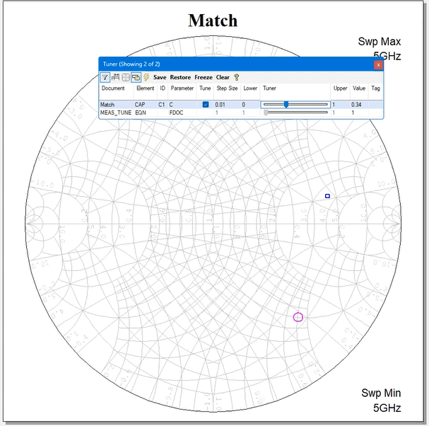
Step 51: Set the value of the capacitor to approximately 0.34pF.
Configuring Inductance
Step 52: Select the Match schematic from the tabbed documents.
Step 53: Select the wire connecting the Port and the Spiral Antenna and click Delete.
Step 54: Select Elements from the left panel and expand Lumped Elements.
Step 55: Select Inductor and choose IND from the expanded list.
Step 56: Click and drag the inductor into the schematic and click to place.
Step 57: Click and drag the port to make a connection with the inductor.
Step 58: Double-click the inductor to edit the element options.
Step 59: Check the box for Tune to make the inductor value tunable.
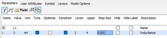
Step 60: Set the L1 value to 2nH.
Step 61: Check the Constraint box. Set the lower constraint to 2 and the upper constraint to 4 with a Step Size of 0.001. This will tune the inductor value between 2nH and 4nH using increments of 0.001nH.
Step 62: Click OK. The inductor value has been added as a tunable item in the Tuner and the value is color-coded blue in the schematic.
Tuning the Inductor
Step 63: Select the Match Smith Chart from the tabbed documents.
Step 64: Slide the tuning bar for the inductor value or use the right arrow key on the keyboard to increase the value of the inductor.
Note: View the circle move on the Smith Chart to adjust based on the inductor value. Zoom into the Smith Chart for improved accuracy by selecting CTRL and rolling the mouse wheel up. This will center the zoom on the mouse.
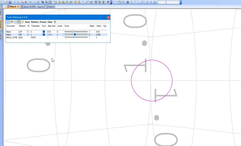
Step 65: Set the value of the inductor to approximately 2.892nH.
Perform Antenna Matching with AWR
Step 66: Close the tuning window and press the Home key to return to the full graph size for the Smith Chart.
Step 67: Right-click on the Smith Chart and select Options.
Step 68: Select the Grid tab and click to deselect the Admittance Grid to improve visibility.
Step 69: Right-click on the Smith Chart and select Add Marker.
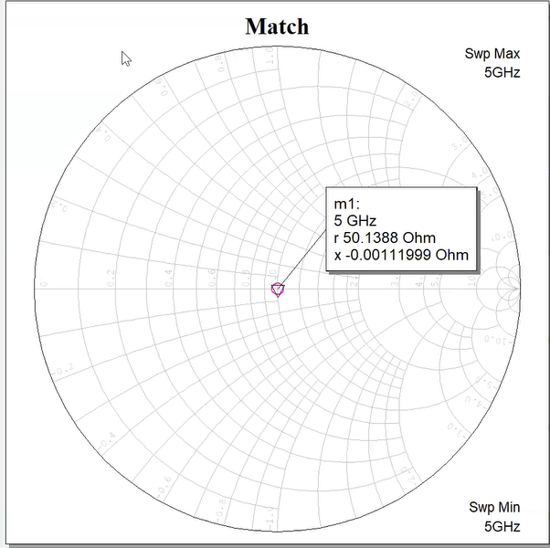
Step 70: Click the center of the symbol for the matched antenna.
Step 71: View the values of the resistance and admittance to ensure accurate antenna matching.
Wrap Up & Next Steps
Efficiently and accurately perform antenna matching by tuning capacitive and inductive values with AWR Microwave Office. Learn more about AWR and get a free trial here.
