PCB Walk-through 10: 3D Modeling
This walk-through demonstrates complete STEP Model mapping and collision detection. After you complete this topic, you will be able to:
- Setup STEP mapping for 3D Models
- Perform collision detection
- Cross-probe between 2D and 3D to resolve collisions
To follow along, continue working with the design completed in PCB Walkthrough 9 or open the provided board file in the folder directory, PCB Walkthrough 10_3D Modeling.
 Open in New Window
- Select the Color button from the toolbar.
- Set the desired view. Click OK.
Note: The view used in this video is as follows:
Stack-up: Select All except Powerplane_1 and Bottom
Area: Select All
Geometry: Select All except Dimension
Components: Select All
Manufacturing: Remove All
Drawing Format: Remove All
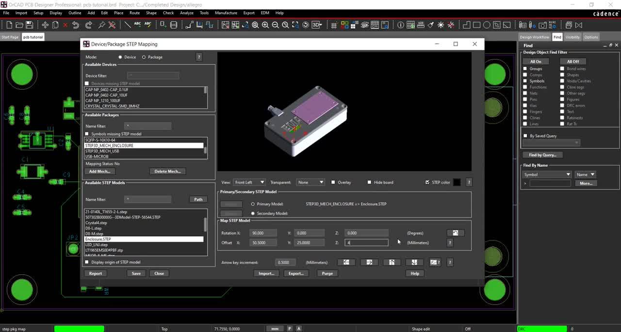
- Select Setup > Step Mapping from the menu.
Note: If you are unsure where your STEP models are stored, select Path under Available STEP packages. This will give you the path for the STEP Model Library.
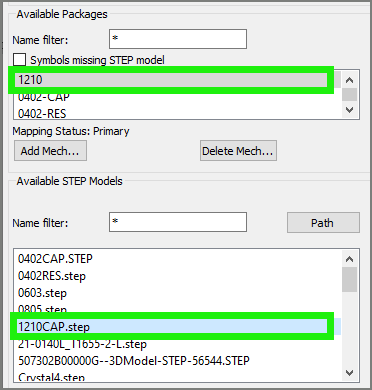
- Select 1210 from the Available Package window.
- Select the 1210CAP.step model from the Available STEP Model window.
- Select Save.
- Complete the STEP Mapping for all the components using the table below:
Note: If needed, set the x, y, or z rotation and the x, y or z offset according to the provided table. To set the rotation and offset, either type the numbers in the desired location or use the increment button. If any PCB footprints have been downloaded from Ultra Librarian through the unified search, the STEP Mapping is already completed for these components.
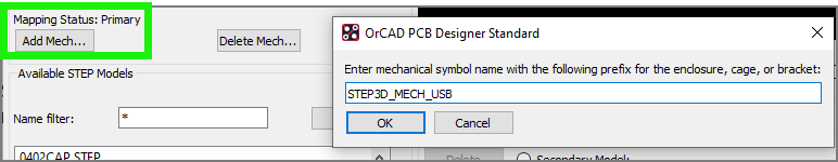
- Select Add Mechanical.
- Enter the name STEP3D_MECH_USB and click OK.
- Map USB.STEP to the new mechanical package using the table below:

Note: Under View, select preset views to ensure the STEP file is mapped correctly.
- Select Save.
- Select Add Mechanical.
- Enter the name STEP3D_MECH_ENCLOSURE and click OK.
- Map Enclosure.STEP to the new mechanical package using the table below:

Note: Using the 3D Canvas in OrCAD we will be able to turn this off and on to view our board.
- Select Save and Close.
- Select the 3D button from the toolbar or Display > 3D View from the menu.
Note: You can select which layers are visible in the visibility tab. You can select which models are visible in the symbols tab.
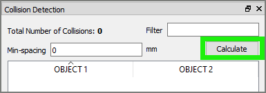
- Select the Collision Detection tab and select Calculate.
Note: If this tab is not visible, select View > Windows > Collision Detection from the menu. The problem components will appear in the window.
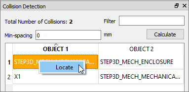
- Right click on an item and select Locate.
Note: This will make the component flash for easy detection. You can also select the component from the list. This will highlight the component.
- Select Setup > Preferences from the menu.
Note: Here you can configure the 3D canvas.
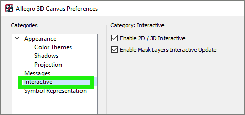
- Select Interactive and Enable 2D/3D Interactive. Select OK.
Note: To rotate the board hold down the shift key and middle mouse button or you can choose preset views by selecting View > Camera in the menu.
- Set up a split screen between the PCB and the 3D Canvas.
- Click to move the connectors X1 and JP2 in the PCB to line up with the existing cutout on the enclosure.
Note: The changes will appear automatically in the 3D view once the part is placed.
- Re-route the connections.
Note: Delete the existing traces. In the Design Window, select Interconnect > Manual Routing > Add Connect. Click to place the trace. Right click and select Done when finished. In the Design Workflow, select Display Status to confirm the routing.
- Select Setup > Step Mapping from the menu.
- Select the STEP3D_MECH_USB in the Available Package Window.
- Change the mapping of the mechanical package using the table below:

- Select Save and Close.
- Select the 3D button from the toolbar.
- In the Collision Detection tab, select Calculate.
Note: The errors have been resolved and only the collision between X1 and the USB is reported.
- In the 3D Canvas, select File > Export.
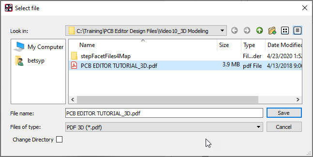
- Select PDF 3D as the file type.
- Name the file and click OK.
