PCB Walk-through 2: Mechanical Symbols
This walk-through demonstrates how to create and place mechanical symbols. After you complete this topic, you will be able to:
- Create a mounting hole
- Place mechanical symbols on your PCB
To follow along, continue working with the design completed in PCB Walkthrough 1 or open the provided board file in the folder directory, PCB Walkthrough 2_Mechanical Symbols.
 Open in New Window
Note: Included in the design files for PCB-Walk-through 2: Mechanical Symbols, is a mechanical library. If you do not want to create the mechanical symbol, copy the .bsm and .dra files included in the mechanical library and paste the files in the standard PCB footprint library: C:\Cadence\SPB_17.4\share\pcb\pcb_lib\symbols
- Select File > New from the menu.
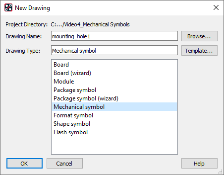
- Select Mechanical Symbol as the Drawing Type.
- Assign Mounting_hole1 as the Drawing Name.
- Select Browse and select the path to the PCB symbol library: C:/Cadence/SPB_17.4/share/pcb/pcb_lib/symbols
- Select Open and OK.
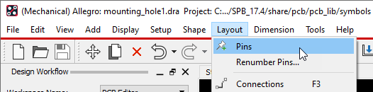
- Select Layout > Pins from the menu.
- Select View > Windows > Options from the menu.
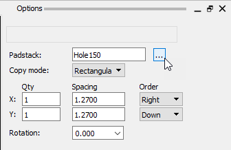
- Browse for a padstack and select Hole 150.
- Select View > Windows > Command from the menu.
- In the Command Window, type x 0 0 and Enter to place the padstack at the origin.
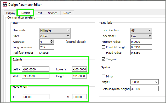
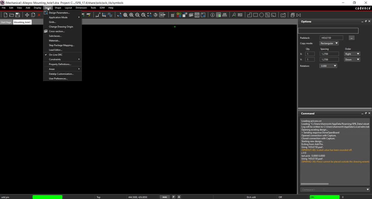
Note: If you receive an error that the pin cannot be placed outside of the drawing extents you need to change the origin. Select Setup > Design Parameters > Design. Under Move Origin, add 100 in the x and y locations to move origin. Click OK.
- Select Shape > Circular from the menu.
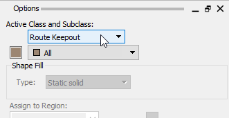
- In the Options tab, select Route Keepout and Top as the Active Class and Subclass.
- Click to place at the origin.
- In the Command Window, type x 3 and Enter to define the radius.
Note: This sets the radius of the circle. You can also drag the circle to the desired size and click to place.
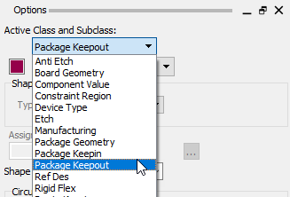
- In the Options tab, select Package Keepout and All as the Active Class and Subclass.
- Select Place Circle under Circular Shape Creation.
- Set the Radius as 3.
- Click to place the keepout.
- Right Click and select Done.
- Select File > Save from the menu.
- Open the PCB design.
- Select Place > Mechanical Symbol from the menu.
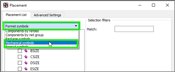
- In the Placement List, select Mechanical symbols from the drop-down.
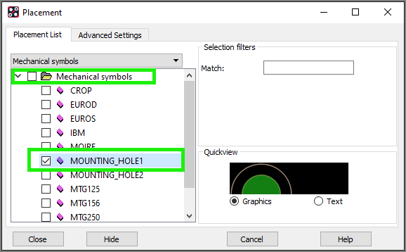
- Check the box next to Mounting_hole1.
- Click to place on the board.
- Repeat this process and place four mounting holes.
- Close the placement window.
Note: Make sure to Close the placement window. Do not X out the window or the last hole will not be placed. To move the mounting hole, select Setup > Application Mode > Placement Edit from the menu. Click to select the hole and click to place.