PCB Walk-through 7: Design Rule Check
This walk-through conducts a final design rule check (DRC) which is necessary to prepare the board for manufacturing. After you complete this topic, you will be able to:
- Run a Design Rule Check
- Identify and correct DRC errors
To follow along, continue working with the design completed in PCB Walkthrough 6 or open the provided board file in the folder directory, PCB Walkthrough 7_DRC.
 Open in New Window
- In the Design Workflow, select Utilities > Display Status.
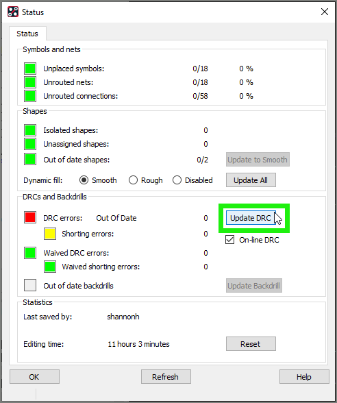
- Select Update DRC.
Note: There are no DRC errors for the design. For the purpose of this tutorial, we will create and resolve a DRC error.
- Close the Display Status Window.
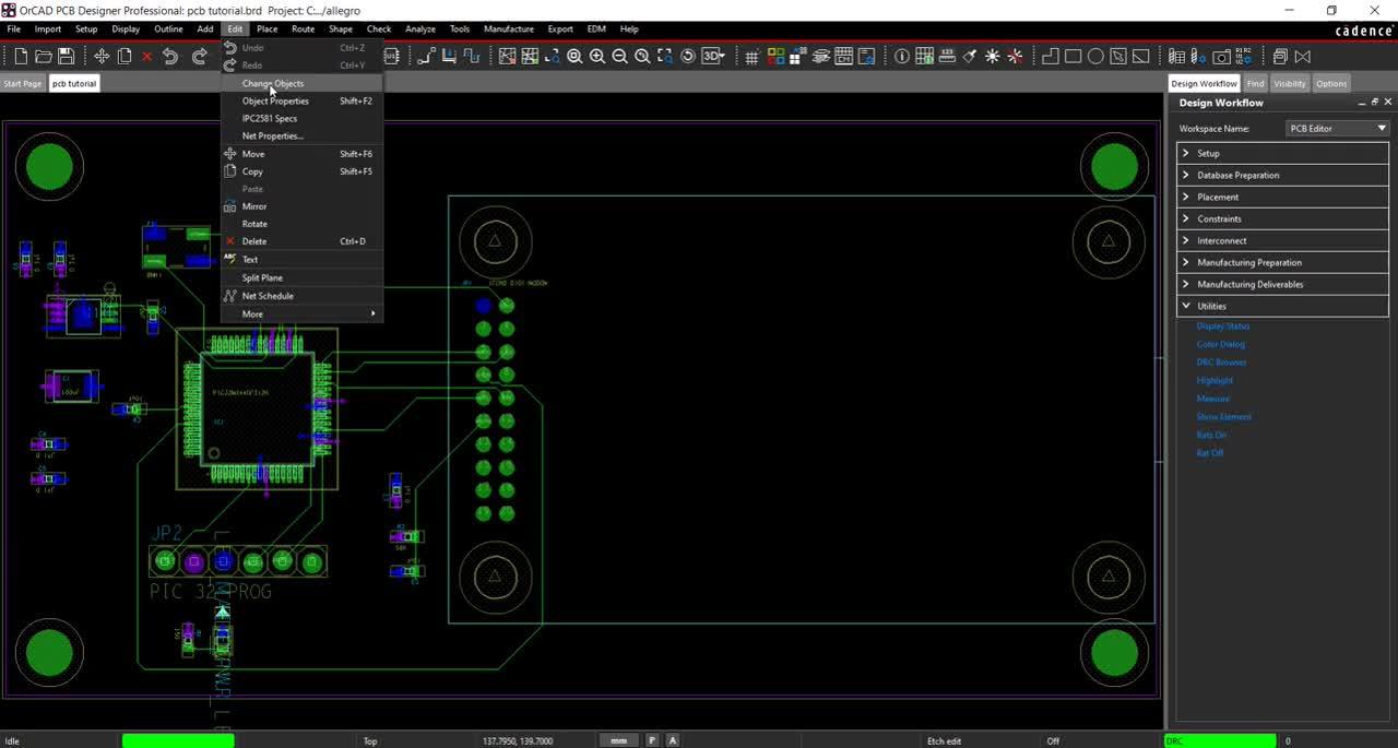
- Select Edit > Change Objects from the menu.
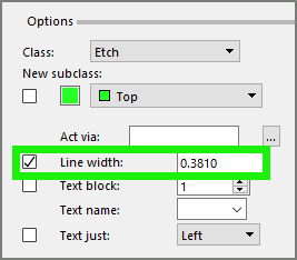
- In the Options tab, select Line width and add a value of 0.381.
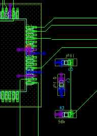
- Select a trace from IC1.
- Right click and select Done.
- In the Design Workflow, select Utilities > Display Status.
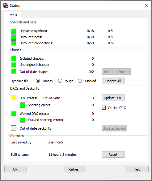
- Click the yellow button next to DRC errors to view the DRC report.
- Select the coordinate to be brought to the location on the PCB or look at the PCB for the DRC marker.
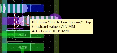
- Mouse over the DRC error for additional information.
- Close the Display Status Window.
- In the Design Workflow, select Utilities > DRC Browser.
Note: Here you can view all the DRC errors on the board and browse by category. Select the coordinates to be brought to the location on the PCB.
- Close the DRC Browser.
- Select Edit > Change Objects from the menu.
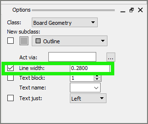
- In the Options tab, change the Line width back to 0.28.
- Click the trace with the DRC Error.
- Right Click and select Done.
Note: The DRC error is resolved and the marker is removed.