
Assign Voltage Values for DC Nets
Step 1: Open the provided design in OrCAD X Presto.
Step 2: To assign DC voltages, you can select the constraint manager icon in the constraint panel or select Electrical Analysis > Constraint Manager from the menu.
Step 3: Here, you can define constraints for the design including properties for nets. Select the Properties tab then select General Properties.
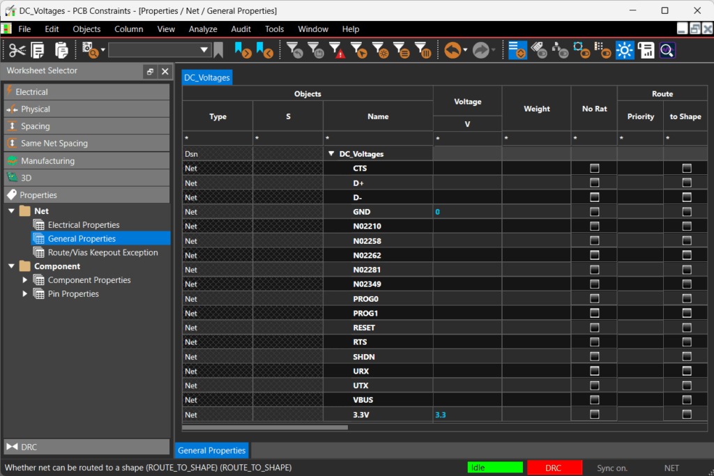
Step 4: Here you can view all the nets in the design. Assign 0V to GND and 3.3V to the 3.3V net.
Step 5: Close the constraint manager window.
Defining Net Colors
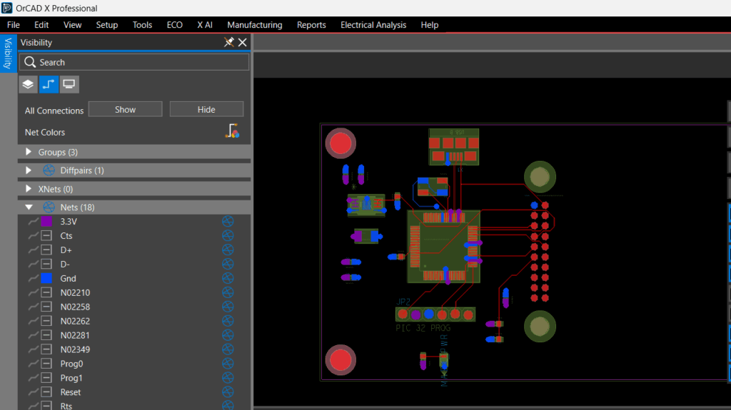
Step 6: Back in the PCB canvas, you can assign different colors to nets in the design for efficient identification of power and ground. Select the Visibility tab.
Step 7: Select the Net tab. This lists out all the nets in the design and provides a centralized location for defining colors as well as turning ratsnest visibility on and off.
Step 8: Select the box next to 3.3 V and select the desired color.
Step 9: Select the box next to GND and select the desired color.
Step 10: Now, in the PCB canvas, you can see the colors have been assigned to ground and power.
Verifying Voltage Values for DC Nets
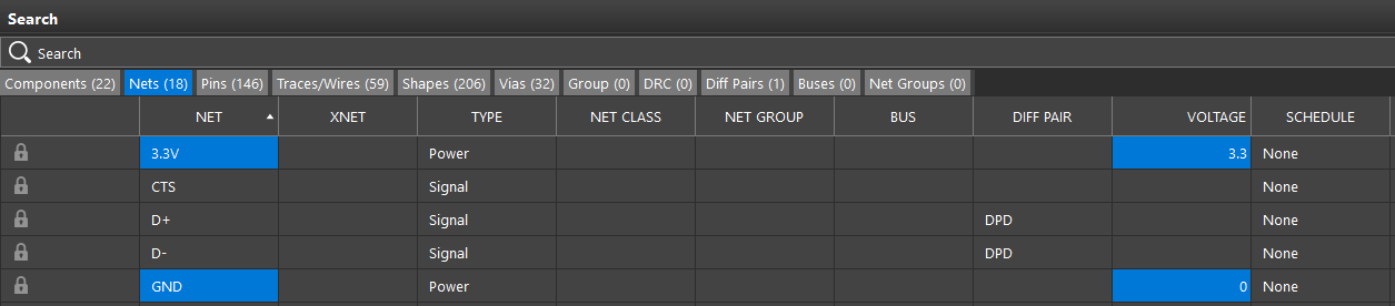
Step 11: To verify that the voltage properties have been set, open the Search Panel.
Step 12: Reset the search if necessary, then select the Net tab.
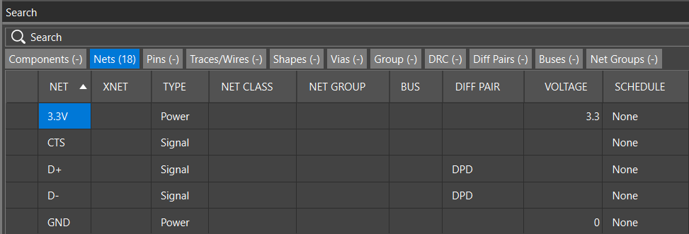
Step 13: Identify the GND and 3.3V nets. The appropriate voltages have been assigned. With the voltages assigned, these can now be used within the PCB design environment to accurately route the design, add copper pours, perform SI/PI analysis, and more.
Assign Voltage Values for DC Nets
Step 1: Open the provided design in OrCAD X PCB Designer.
Step 2: To assign DC voltages, you can select the constraint manager icon on the toolbar or Setup > Constraints from the menu.
Step 3: Here, you can define constraints for the design including properties for nets. Select the Properties tab then select General Properties.
Step 4: Here you can view all the nets in the design. Assign 0V to GND and 3.3V to the 3.3V net.
Step 5: Close the constraint manager window.
Defining Net Colors
Step 6: Back in the PCB canvas, you can assign different colors to nets in the design for efficient identification of power and ground. Select the Color icon from the toolbar or Setup > Colors from the menu.
Step 7: Select the Net tab. This lists out all the nets in the design.
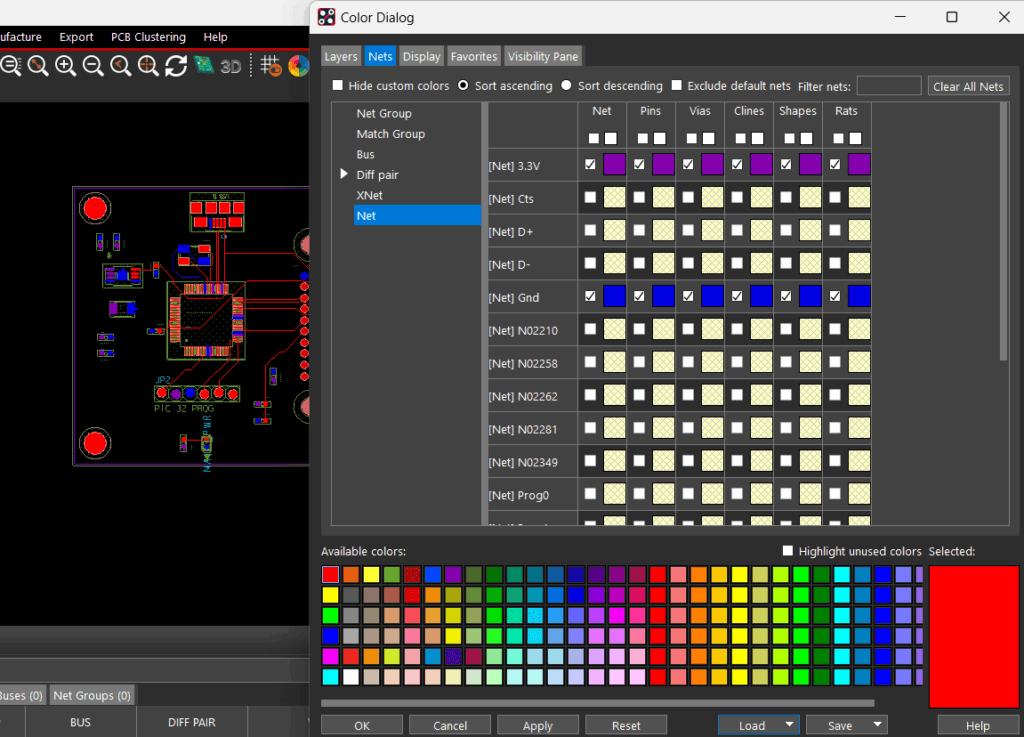
Step 8: Select a color in the available colors then select the box for the 3.3 V net.
Step 9: Select a color in the available colors then select the box for the GND net. Click OK.
Step 10: Now, in the PCB canvas, you can see the colors have been assigned to ground and power.
Verifying Voltage Values for DC Nets
Step 11: To verify that the voltage properties have been set, select Display > Windows > Search.
Step 12: Reset the search if necessary, then select the net tab.
Step 13: Identify the GND and 3.3V nets. The appropriate voltages have been assigned. With the voltages assigned, these can now be used within the PCB design environment to accurately route the design, add copper pours, perform SI/PI analysis, and more.

