Before a PCB is put into production, performing SPICE simulations can make the difference between a pre-production revision and a costly board respin. Simulations, such as AC sweeps, are essential to analyze potential faults, undesired circuit behavior, and even component failures. An AC sweep simulation can be used to show the behavior of a circuit in the frequency domain and verify functionality. With PSpice, you can use AC Sweep analysis to perform:
- Frequency Response Analysis
- Noise Analysis
- Stability Analysis
- Filter Design and Analysis
- Performance Analysis
This quick how-to will provide step-by-step instructions on how to perform an AC sweep simulation in PSpice.
To follow along, download the provided materials above the table of contents.
How-To Video
 Open in New Window
Creating an AC Sweep Simulation Profile
Step 1: Open the provided design in OrCAD PSpice Designer.
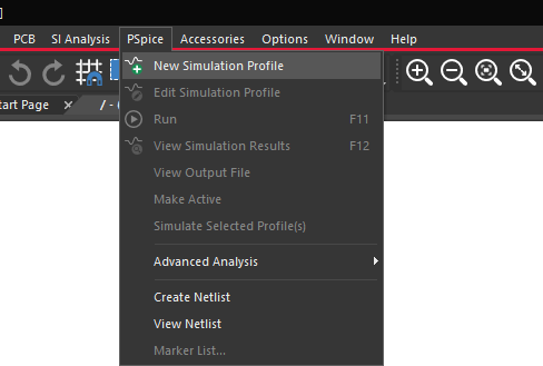
Step 2: Select PSpice > New Simulation Profile from the menu.
Step 3: Name the simulation profile AC_Sweep and click Create.
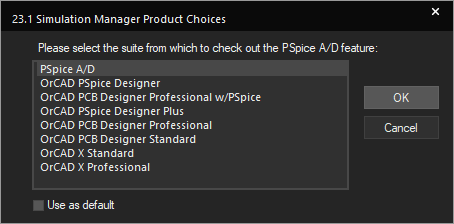
Note: If the Simulation Manager Product Choices window opens, select the appropriate license and click OK.
Step 4: Select AC Sweep from the Analysis Type drop-down menu.
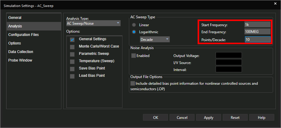
Step 5: Enter the following simulation settings:
- Start Frequency: 1k
- End Frequency: 100MEG
- Points/Decade: 10
Note: A value of 100M would be interpreted as 100 millihertz. Use “MEG” to signify the MEGA- prefix. Prefixes are not case-sensitive.
Step 6: Click OK to save the settings and close the window.
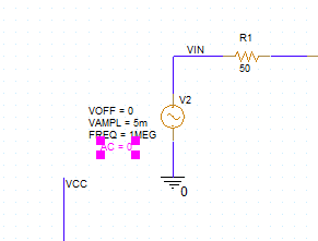
Step 7: Double-click the value AC = 0 on the sine source V2.
Note: An AC source component must be defined before the simulation can be run.
Step 8: Enter 1 for the value and click OK.
Placing Probes
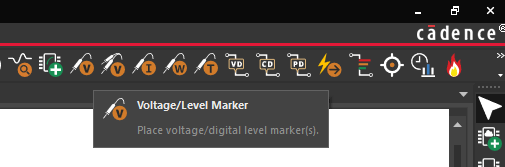
Step 9: Select the Voltage/Level Marker button from the toolbar.
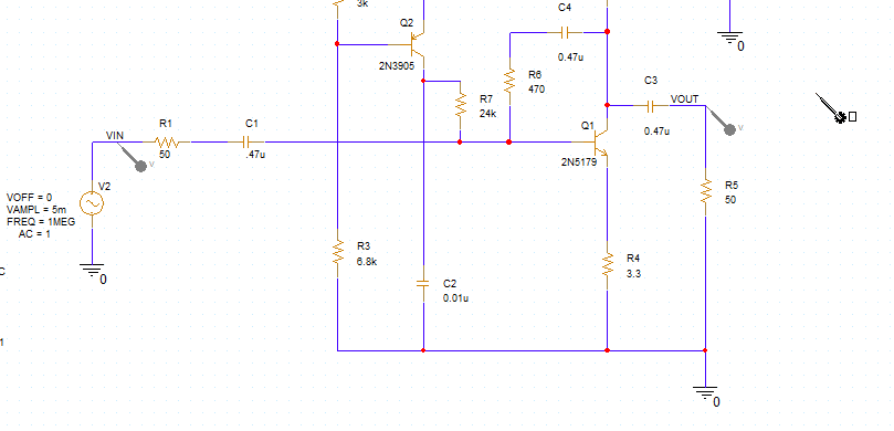
Step 10: Click to place probes at the VIN and VOUT nets. When finished, right-click and select End Mode.
Running an AC Sweep Simulation
Step 11: Select PSpice > Run from the menu or the Run button on the toolbar to start the simulation.
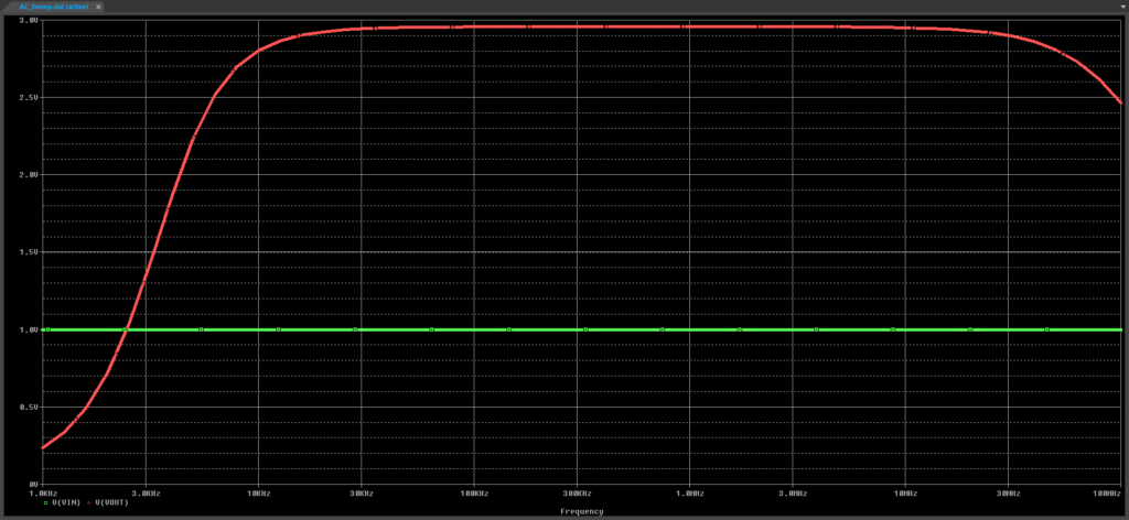
Step 12: The PSpice A/D window opens. View the simulation results. The VIN input remains constant throughout the sweep. The output voltage VOUT shows that the RF amplifier circuit is effective between approximately 20kHz and 30MHz.
Step 13: Close the PSpice A/D window.
Performing a Noise Analysis
Note: Noise Analysis calculates and shows noise contributed from noise-generating devices in the circuit, propagated to a specific output net. Noise Analysis can be used to predict unwanted noise contributions and analyze the circuit’s response to ensure successful operation.
Step 14: Select PSpice > Edit Simulation Profile from the menu.
Step 15: Check Enabled under Noise Analysis.
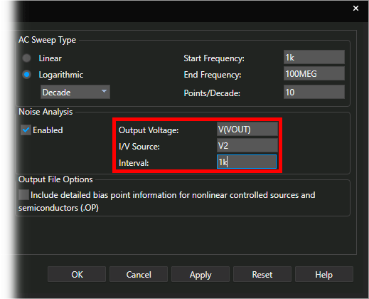
Step 16: Configure the following settings:
- Output Voltage: V(VOUT)
- I/V Source: V2
- Interval: 1k
Note: The Output Voltage determines the net at which the calculated noise is to be propagated to. I/V Source defines the input (current or voltage) source for the circuit. The Interval determines the frequency interval at which to calculate and record the noise contributions.
Step 17: Click OK to save the settings and close the window.
Step 18: Select PSpice > Run from the menu.
Note: The plot window will open to the signal plot.
Step 19: Select each trace in the legend and press Delete on the keyboard.
Step 20: Select Trace > Add Trace from the menu.
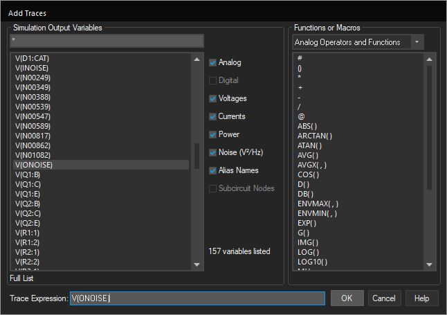
Step 21: Select V(ONOISE) from the Simulation Output Variables list. Click OK.
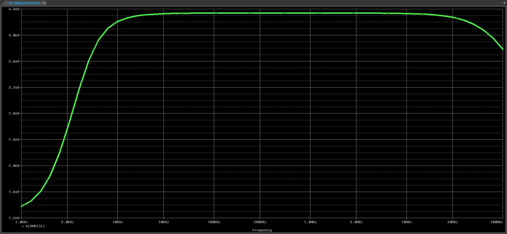
Step 22: View the results. The output noise has been plotted and follows a similar pattern compared to the original signal, but with lower magnitudes.
Wrap Up & Next Steps
Perform an AC sweep to ensure proper circuit behavior in the frequency-domain and verify high-frequency operation in PSpice. Test out this feature and more with a free trial of OrCAD. Want to learn more about PSpice? Get access to free how-tos, courses, and walk-throughs at EMA Academy.
