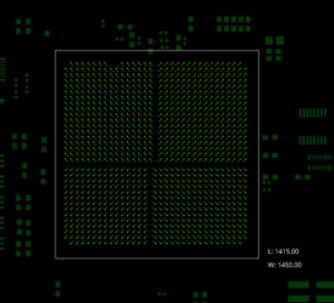
Preconfigure Fanouts for Large Components
Location: PCB Canvas
It is recommended to pre-fanout large pin count devices to ensure intended via usage or consider constraint regions. These should be locked in the design and/or included in the PCB footprint for reuse across multiple designs.
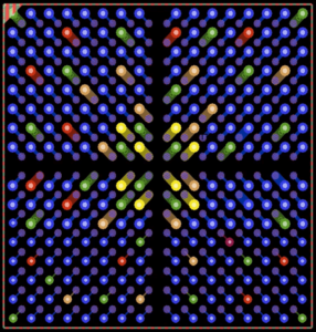
Preplace High-Speed Via Structures
Location: PCB Canvas
High-speed via structures should be pre-placed on the PCB to ensure accuracy.
Complete Copper Pouring
Location: PCB Canvas
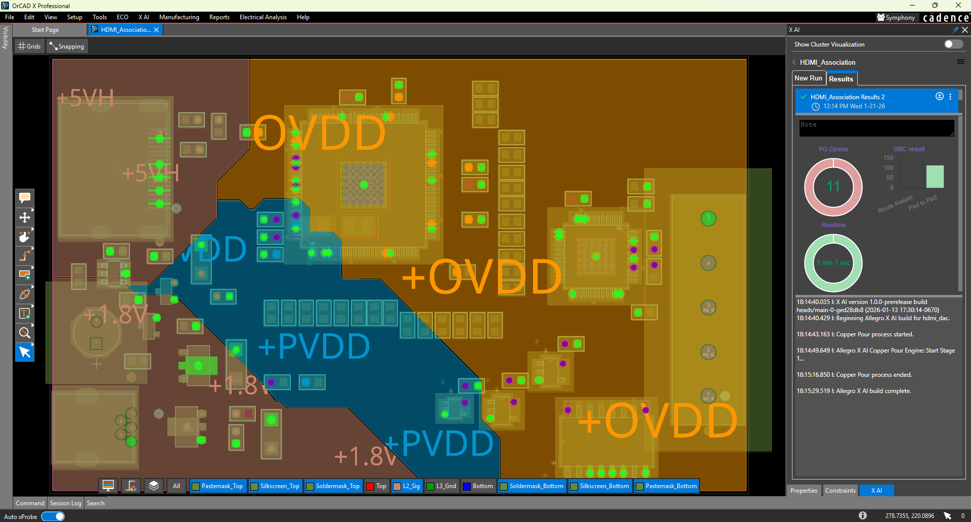
The majority of power and ground shapes should be added before routing. These should be added as dynamic shapes to allow Allegro X AI to route within or across a dynamic shape but at a high cost if alternative solutions cannot be found.
Define Region-Based Constraints
Location: PCB Canvas
Define regions for BGAs and other high pin density devices where reduced line width and spacing is required. Keep region-based constraints simple and avoid overlap if possible. The X AI router will respect region-based rules for line width, spacing, and via usage.
