Setup: Required Inputs During Allegro X AI
The following inputs should be in Allegro X AI to accurately communicate your design intent and ensure the best results:
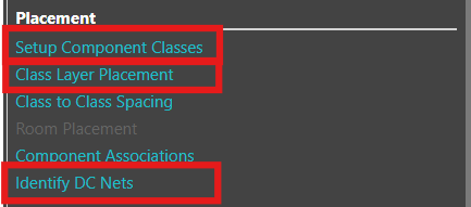
Identify DC Nets
Location: Allegro X AI
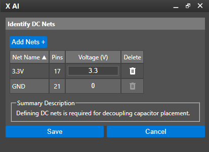
Identify DC Nets in the Allegro X AI panel, sets up power and ground, identifying the varying voltages, power nets, and ground nets in the design. Ideally these values are defined in the PCB by assigning DC nets with a voltage property in the constraint manager but can also be done in the Identify DC Nets section. When using Allegro X AI for component placement, this is required for decoupling capacitor placement.
If voltage values have been assigned in the schematic or PCB, launch the Identify DC Nets section, review the automatically configured DC nets, and save the information.
If voltage values have NOT been assigned in the schematic or PCB, launch the Identify DC Nets section, add the power and ground nets for the design, and define the corresponding voltage values.
Need Help? Get step-by-step instructions for defining power and ground nets here: Allegro X AI Setup Instructions
Component Classes
Location: Allegro X AI
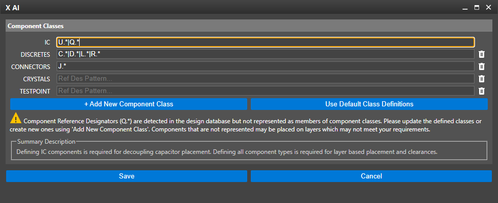
Component classes map the reference designators in the design to types of components. Naming assignments should be set up for all components but are most important for ICs. By default, Allegro X AI follows IEEE guidelines for naming conventions; however, IC naming conventions can vary per company requirements. It is important to verify and update the following component classes with the specific reference designators used in your design:
- ICs: Default naming convention is U
- Connectors: Default naming conventions are J and P
- Crystals: Default naming convention is Y
- Testpoints: Default naming convention must be TP
New component classes can be added in the Component Class setup window and the corresponding reference designators can be mapped. This is important for the following types of components:
- Transformers
- Zener Diodes
- Batteries
- Fuses
- Ferrite Beads
- Relays
- Mechanical Components: Although they can be named, the Allegro X AI engine does not attempt to Autoplace them.
New, unique component classes can be created to drive certain components to top and/or bottom layers or to allocate extra clearance.
Need Help? Get step-by-step instructions on how to configure component classes here: Allegro X AI Setup Instructions
Class Layer Assignment
Location: Allegro X AI
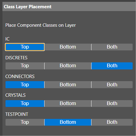
Define whether component class should be placed on the Top, Bottom, or Both Sides of the PCB. This will dictate where Allegro X AI can place components in the design.
You can also override default configurations to place specific reference designators on designated layers without creating new component classes.
Note: Embedded layers are not supported with Allegro X AI at this time.
Recommendations:
If test points are through-hole be sure to select Both for the layer.
For thru-hole components select Top.
Need Help? Get step-by-step instructions for defining class layer assignments here: Allegro X AI Setup Instructions
