With the board outline defined and mechanical features placed, the next step in the design process is to place the components on the PCB. OrCAD X Presto offers a number of tools and features to place components as efficiently as possible, including:
- Place by coordinates
- The Search Panel
- Cluster Placement
- Series Placement
- Cross-placement with the schematic
- Placement based on the schematic
This quick how-to will provide step-by-step instructions on how to place components on a board in OrCAD X Presto with each method.
To follow along, download the provided files above the table of contents.
How-To Video
 Open in New Window
Place Components from the Search Panel
For this example, components have been quick placed to the top edge of the board. To learn how to quick place components in OrCAD X, see our how-to here.
Step 1: Open the provided board file in OrCAD X Presto.
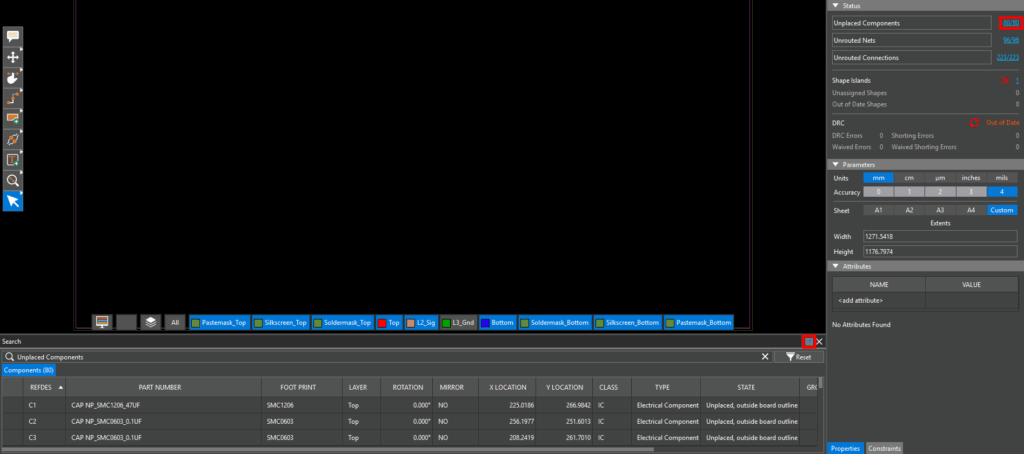
Step 2: Select the hyperlink for Unplaced Components in the Properties panel under Status to open the Search panel. Select the pushpin to disable Auto Hide to prevent the panel from closing.
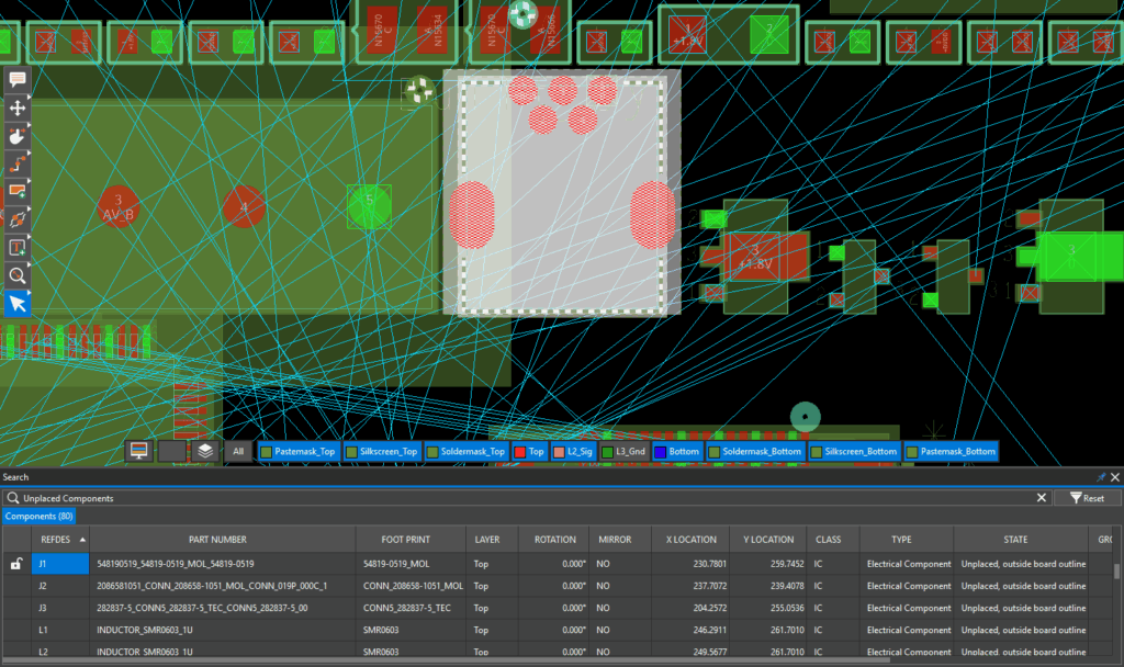
Step 3: In the Search panel, scroll down to connector J1. Double-click the listing to select the part and zoom into it.
Step 4: Select the Move mode from the toolbar.
Step 5: Select connector J1 to attach it to your cursor.
Step 6: To place a component, move the connector to the desired position and click again to finish. Press R on the keyboard to rotate as needed.
Step 7: Back in the Search Panel, click the Lock icon next to J1 to lock the connector. This will ensure it doesn’t move when other components are being placed or adjusted.
Place Components on the PBC: Coordinates
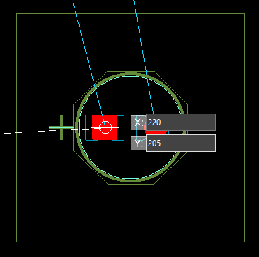
Step 8: To place components on the PCB in a specific location, coordinates can be used. Select LED1 at the top of the component group.Press Tab on the keyboard to easily assign the coordinates for the component. enter 220 for X.
Step 9: Press Tab on the keyboard. Enter 205 for the Y coordinate then press Enter.
Note: Coordinates can also be set in the properties panel with the desired component selected.
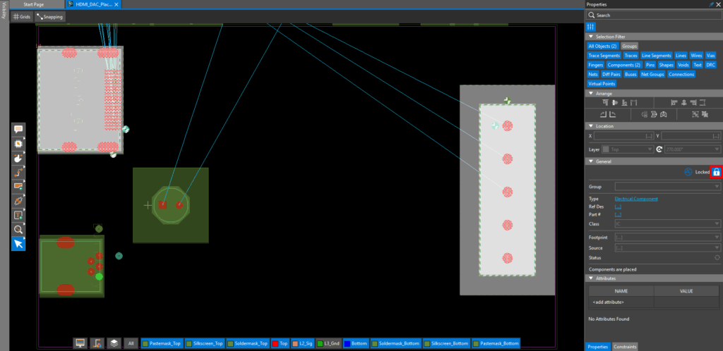
Step 10: Components can also be locked from the Properties panel. Select the Lock icon in the Properties panel to lock the LED.
Place Components on the PCB: Series Placement
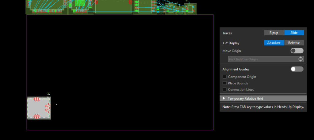
Step 11: Right-click the Move mode in the toolbar and select Place.
Step 12: The Place widget opens. To place components on the PCB one after the other, ensure Series is selected as the placement type.
Step 13: Click and drag to select HDMI connector J2 and output connector J3 in the Search panel.
Step 14: Click to place J2 on the canvas. J3 is automatically selected. Click to place J3.
Step 15: Choose theSelect mode from the toolbar.
Step 16: Hold CTRL on the keyboard and select J2 and J3. Click the Lock icon in the Properties panel to lock the connectors.
Place Components on the PCB: Cross-Placement from the Schematic
Step 17: Select the Place mode from the toolbar.
Step 18: For more efficient placement optimization for components such as ICs and decoupling capacitors, place components on the PCB with selection in the board’s associated schematic file. At the bottom of the Presto window, ensure Auto xProbe is switched on.
Step 19: Open the provided schematic file in OrCAD X Capture.
Step 20: In Capture, select Options > Preferences from the menu.
Step 21: Select the Miscellaneous tab.
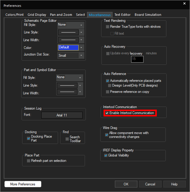
Step 22: Ensure Enable Intertool Communication is checked to allow cross-probing. Click OK.
Step 23: Set up a split-screen configuration with the schematic and PCB.
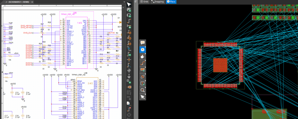
Step 24: Select component U4 in Capture. U4 is attached to your cursor in the PCB canvas.
Step 25: Click to place the IC within the board outline. Press R on the keyboard to rotate as needed.
Place Components on the PCB: Cluster Placement
Step 26: In Capture, click and drag to select the decoupling capacitors for U4.
Step 27: The same parts are selected in Presto. To place components on the PCB in a group, select Cluster in the Place widget. The nine capacitors designated as smoothing capacitors for U4 are now attached to your cursor in a cluster. The cluster can be configured from the Place widget.
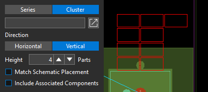
Step 28: Select Vertical to arrange the capacitors vertically. Set the height to 4 to divide the capacitors into columns of four.
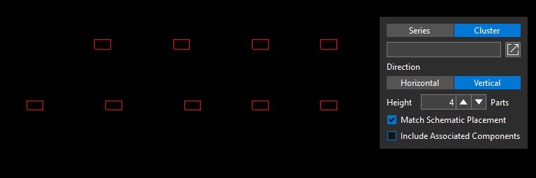
Step 29: If running OrCAD X Professional, parts can be placed how they are laid out in the schematic. To do this, check Match Schematic Placement. The capacitors are arranged as they are drawn in the schematic.
Step 30: Uncheck Match Schematic Placement and click to place all selected capacitors at once in a cluster.
Place Components: Modifying Component Placement
Step 31: Parts can be rotated from the Properties panel or Search panel after placement as well. Select Series in the Place widget to place components sequentially.
Step 32: In the Search panel, scroll down and select U5 to attach it to your cursor.
Step 33: Click to place U5 on the PCB canvas. Choose the Select mode from the toolbar.
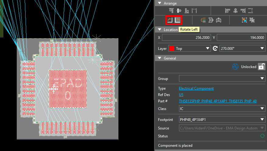
Step 34: Click U5 to select it. In the Properties panel, under Arrange, select Rotate Left or Rotate Right to rotate the placed component.
Step 35: Components can also be rotated from the Search panel. Double-click the cell under Rotation for U5.
Step 36: Select the desired rotation from the dropdown.
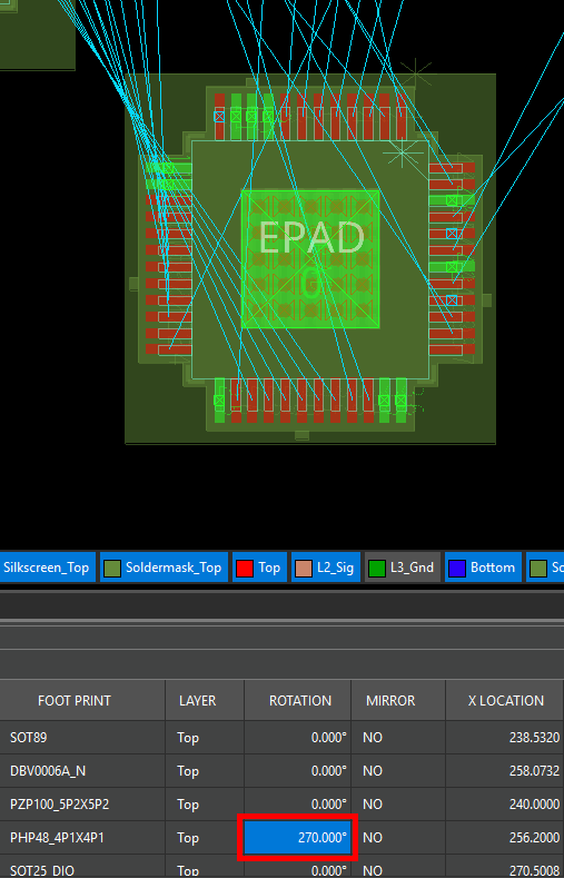
Step 37: Click outside the cell to set the rotation. Click anywhere in the canvas to deselect the component.
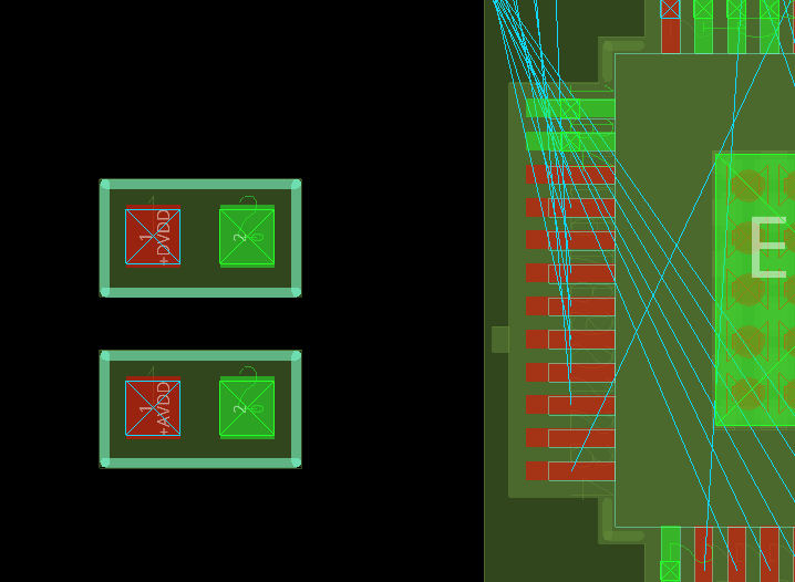
Step 38: By default, new parts are placed on the top side of the board. In situations where space is tight, components can also be placed on the bottom. Select the Place mode from the toolbar. In the Search panel, click and drag to select C20 and C21 to attach the capacitor series to your cursor.
Step 39: Click to place the capacitors in the canvas. Choose the Select mode from the toolbar when finished.
Step 40: Click and drag to select the capacitors in the PCB canvas.
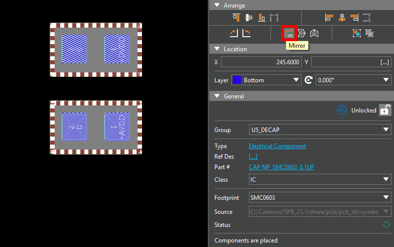
Step 41: Select the Mirror icon under Arrange in the Properties panel to mirror the capacitors. The capacitors are now placed on the bottom layer.
Step 42: This can also be accomplished directly in the search panel. Click and drag to select the cells in the Layer column for C20 and C21.
Step 43: Right-click and select Edit.
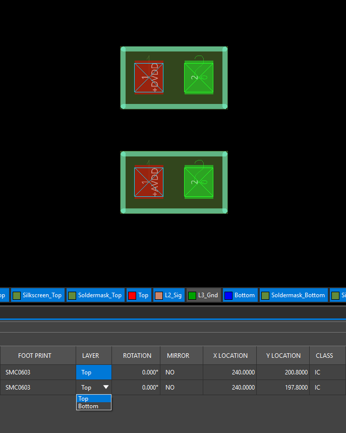
Step 44: Select Top from the resulting dropdown and click outside the cells. The capacitors are returned to the top layer.
Wrap Up & Next Steps
Quickly and easily place components on the PCB using multiple placement methods in OrCAD X. Test this feature and more with a free trial of OrCAD and get more step-by-step instructions for OrCAD X at EMA Academy.

