
Quick Place Components on the PCB
Step 1: Open the provided design in OrCAD X Presto.
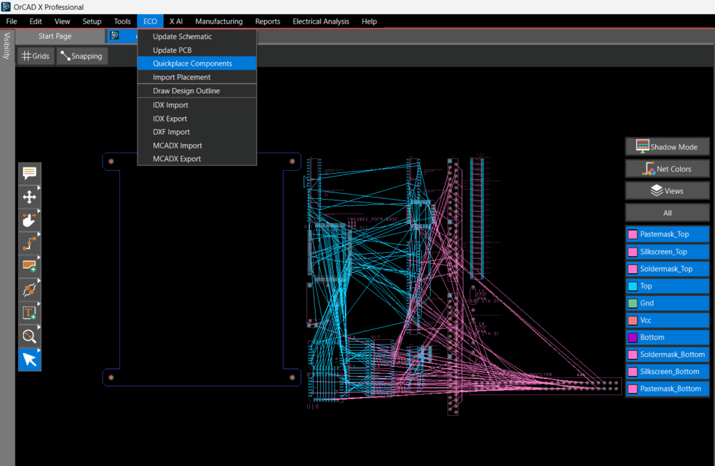
Step 2: Select ECO > Quickplace Components from the menu. The components have been placed along the longest side of the board.
Assigning Colors for Nets in OrCAD X
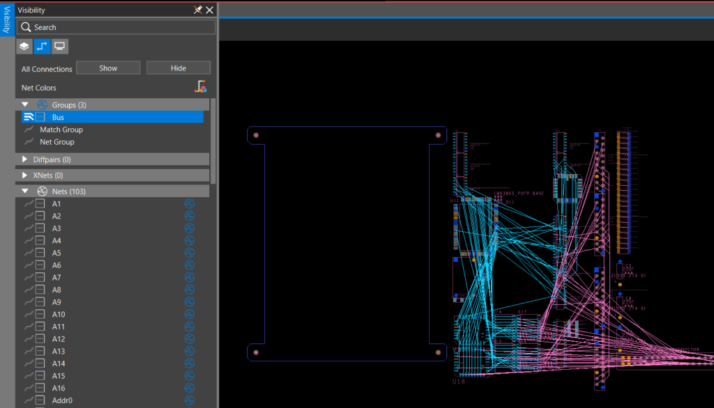
Step 3: Visibility can be improved by configuring ratsnests and colors for nets to optimize component locations and rotation during placement. Select the Visibility tab.
Step 4: Select the Nets tab. All the nets are listed in the design.
Step 5: Select Hide to hide all ratsnest connections.
Step 6: Colors can be assigned to nets for easy identification in the PCB canvas. To assign colors to nets, expand the section for Nets.
Step 7: Locate the Gnd net and select the box next to it. Choose the desired color then click another area in the nets panel to close the color selection dialog box.
Step 8: Locate Vcc net and select the box next to it. Choose the desired color then click another area in the nets panel to close the color selection dialog box.
Configuring Ratsnest Visibility in OrCAD X
Step 9: Ratsnest visibility can be turned on and off for individual nets, groups of nets, or components. With the Nets section still expanded, select the ratsnest icon for individual nets in the design to see the connections. Select the ratsnest icon again to disable the connection lines.
Step 10: To enable the ratsnests for groups of nets, expand the section for Groups. Select the ratsnest icon for Bus. All the nets included in the bus have been activated. Select the ratsnest icon again to disable the ratsnest.
Step 11: Ratsnests for components can also be activated. Select a component in the PCB canvas.
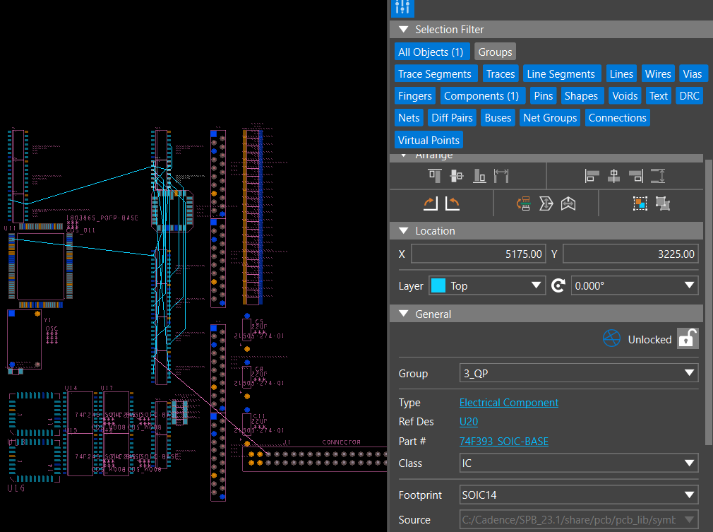
Step 12: Select the Properties tab. Scroll to the General properties for the component and toggle the ratsnest icon to enable/disable the visibility of the connections for the component.
Quick Place Components on the PCB
Step 1: Open the provided design in OrCAD X PCB Editor.
Step 2: Select Place > Quickplace components from the menu.
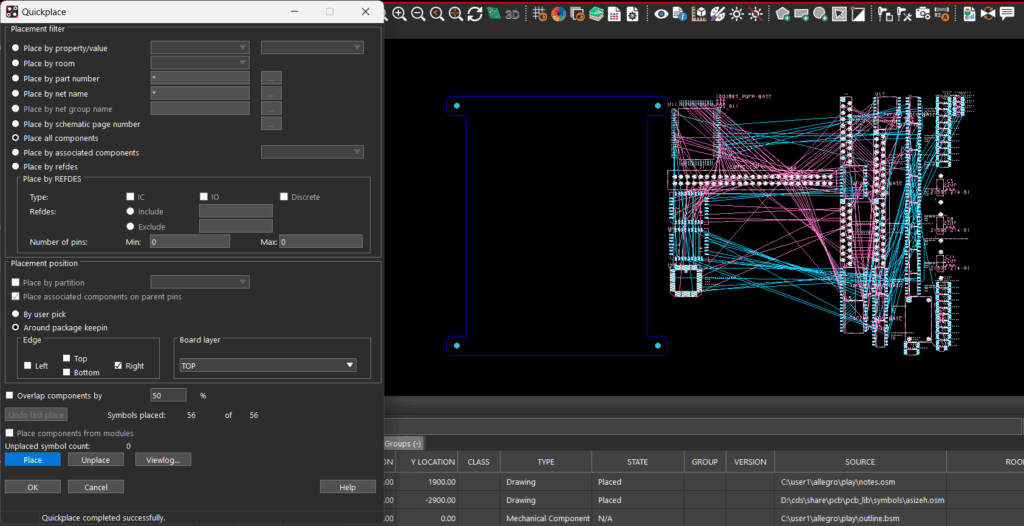
Step 3: In the Quickplace window, you have multiple options to quickplace components including by room, by net name, by reference designator, and more. Ensure Place All Components is selected.
Step 4: Under Placement Position, select Right under Around Package Keepin.
Step 5: Select Place.
Step 6: The components have been placed to the right of the board. Click OK to close the Quickplace window.
Assigning Colors for Nets in OrCAD X
Step 7: Visibility can be improved by configuring ratsnests and colors for nets to optimize component locations and rotation during placement. Select the Color icon from the toolbar.
Step 8: Select the Nets tab. All the nets are listed in the design.
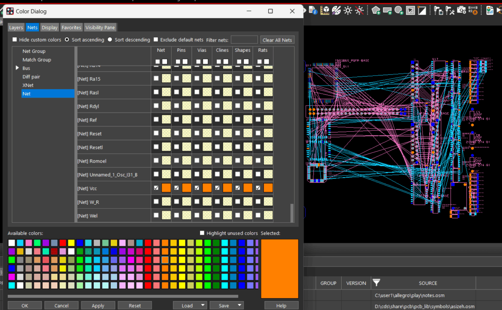
Step 9: Locate the Gnd net. Select a color from the available colors then select the box for Gnd.
Step 10: Locate Vcc net. Select a color from the available colors then select the box for Vcc.
Step 11: Click OK to close the window.
Configuring Ratsnest Visibility in OrCAD X
Step 12: Ratsnest visibility can be turned on and off at the net level, groups of nets, or component level. Select the Unrats All icon on the toolbar.
Step 13: To enable the ratsnests for a net, select Display > Show Rats > Nets. Select the desired net in the PCB canvas to activate the rats line. Repeat this process until all the desired nets are visible.
Step 14: Select the Unrats All icon on the toolbar.
Step 15: To enable the ratsnests for a component, select Display > Show Rats > Components. Select the desired component in the PCB canvas to show the connections.
Step 16: Right click and select Done (F6) when finished.

