Sigrity X
Sigrity Aurora On-Demand Licensing
- Aurora
An on-demand licensing model has been introduced for Sigrity Aurora. With this change, Sigrity Aurora features are delivered through an on-demand packaging framework with an Allegro license.
Advanced Cut Supported in Topology Extraction Workflow
- Topology Explorer
The Topology Extraction Workflow supports the Advanced Cut capability, making it accessible across all license tiers for topology extraction, unlike other workflows that restrict this feature to higher tiers. It includes a Cut Design by Selected Net(s) check box in the Extraction tab of the Topology Extraction Parameters Setup dialog box, which is selected by default to enable cut functionality
Analysis Workflows Documentation
- Aurora
Sigrity Aurora User Guide has been enhanced to include step-by-step instructions and configuration details for the following analysis workflows: Virtual Proto, Design Setup, Impedance, Reflection, Return Path, Power Inductance, and Thermal Workflows.
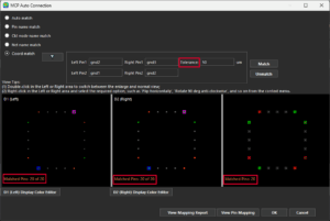 The Margin field is renamed to Tolerance (for Coord match) in MCP Auto Connection dialog box, and the number of matched pins is now displayed. The Pin Mapping Report dialog box now includes clear matched/unmatched section labels.
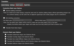 The Conductive Mask Layer Options and Dielectric Mask Layer Options that were previously available under the Rigid-Flex tab of the Translators form have now been separately organized under a new tab called Mask Layers.
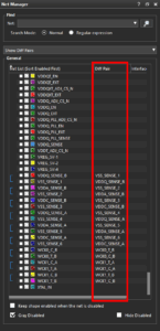 The Net Manager dialog box provides an additional display mode, Show Diff Pairs, to view all the differential net pairs present in a design. When you choose Show Diff Pairs as the display mode, the net manager adds a new column, Diff Pair, to the table that indicates all the differential net pairs.
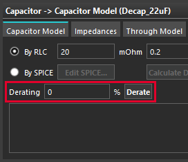 An option to create derated capacitor models has been added in the Capacitor Libraries section.
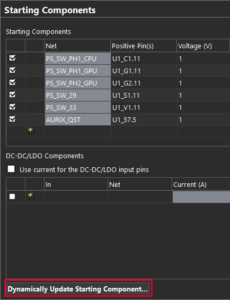 PowerTree now detects mismatches between the starting component settings and the layout netlist and lets you update the power tree using the Dynamically Update Starting Component feature available in Starting Components form.
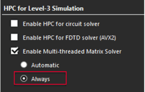 The multithreaded circuit solver is now more robust. For designs that previously encountered convergence or stability issues, selecting the Enable Multi-threaded Matrix Solver option with the Always option in the HPC for Level-3 Simulation form can now resolve certain failure cases.
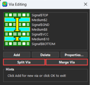
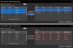 A new button, Add to Selected, is available in the Create Pin Pair – Relative Propagation Delay window. Clicking this button adds a pin pair selected from the left table to an existing match group in the Pin Pairs table, creating a new entry where the selected match group’s name is retained. The cells under the Name column of the Pin Pairs table are editable.
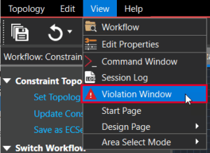 The new Violation panel lets you view the error, warning, and information messages related to a topology extracted from Allegro Constraint Manager into the Constraint Setup workflow in Topology Workbench for signal integrity exploration. To open this panel, select View > Violation Window.
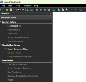 All Sigrity Layout Workbench tools feature an intuitive user interface consisting of reorganized menus, streamlined toolbars and options, and vibrant icons to boost efficiency and productivity. In previously releases, UI improvements were available via the User Improved User Interface checkbox. Starting with 25.1, the checkbox has been removed, and the improved UI is available by default.
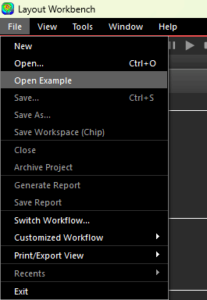 The File menu provides a new option, Open Example, for quick access to the examples shipped with the installation. This option lets you access all samples and examples with a single click with no need to manually search in the install directory.
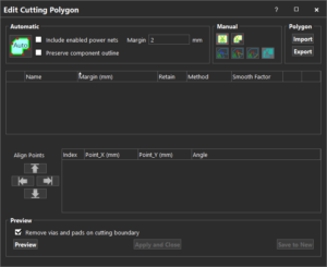 The Edit Cutting Boundary dialog box has been enhanced and renamed to the Edit Cutting Polygon dialog box with several options added to provide advanced polygon cutting capabilities. The dialog box can be accessed from the Summary Cutting Polygon icon on the Processing toolbar.
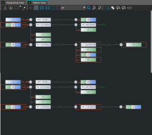 PowerTree supports incremental updates to the topology tree, allowing changes from the schematic to be reflected without rebuilding the entire tree. When a new netlist is generated with minor updates, only the affected portions of the tree are updated. This approach saves time and maintains the existing structure and settings.
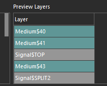 The Reuse Stackup dialog box now shows a preview of the reused stackup results in a dedicated pane called the Preview Layers panel when reusing stackup settings form another SPD file. This capability ensures that the reused stackup results are consistent with your simulation goals.
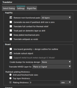 The translation settings available under the Settings tab have been functionally organized under dedicated categories to provide an intuitive experience to Layout Workbench users.
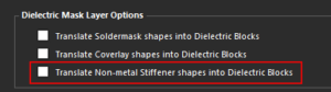 A new setting, Translate Non-Metal Stiffener Shapes into Dielectric Blocks, has been added to convert non-metal stiffener shapes into dielectric blocks during translation. This option is available in the Rigid-Flex tab under Dielectric Mask Layer Options.
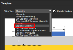 A new transmission line template, Coplanar Stripline, has been added to the Trace Editor dialog box.
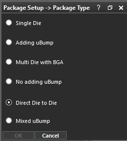 A new package type, Direct Die to Die, is added to the Package Setup > Package Type panel. This package type lets you extract the model between die to die directly without BGA. When using this type, ensure that one of the dies is assigned as the Main Die when selecting components in the Wizard dialog box.
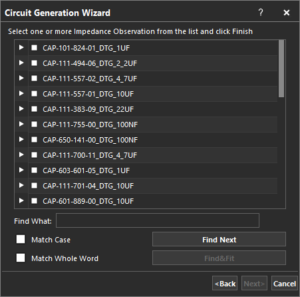 The Circuit Generation Wizard now allows selection of all power nets at once during the Impedance Observation and Decoupling Capacitors setup. The Power Net dropdown includes an option for PowerNets, which allows you to select and display all power nets simultaneously.
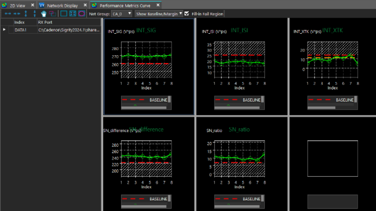
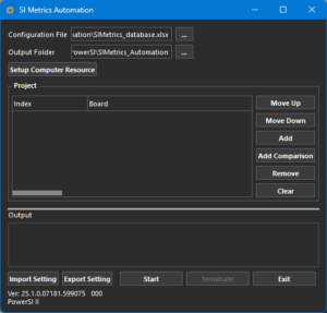 The SI Metrics Automation workflow has been added to automate the PowerSI S-Parameter Assessment workflow. The new workflow provides automated layout-level signal integrity performance evaluation. This workflow can be used to quickly compare up to three board designs with comprehensive signal integrity metrics and waveform visualizations. This workflow is available as a separate executable, SIMetrics_Automation.exe, in the tools/bin directory of your local installation.
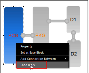 The Multiple Structure Simulation workflow in PowerSI includes several enhancements in the GUI to provide users with more ease and flexibility. The workflow pane in both Diagram View and 2D View is updated to display relevant configuration options. Additionally, you can directly access the details of each block present in a topology by right-clicking and selecting the Load Block button.
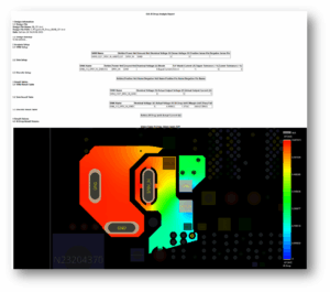
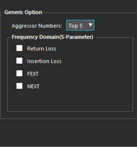 In the S-Parameter Assessment workflow, the Report dialog box now includes new options to include in the simulation report, including frequency domain, time domain, and other performance metrics.
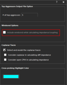 In the ERC – Trace Imp/Cpl/Ref Check workflow, an option to Include Wirebond while Calculating Impedance/Coupling has been added to the Set up ERC Sim Options dialog box. Check this option to view the impedance and coupling in the wirebonds present in the design.
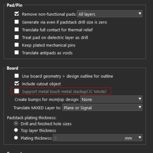 Metal-to-metal touch in IC Mode has been added to Layout Workbench Tools. When disabled, a medium layer is automatically inserted between adjacent metals.
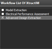 A new workflow, Enhanced Design Extraction, is now available to use in XtractIM. This workflow enables you to solve the RLC between dies and capacitors without BGA, use an existing uBump without adding an extra bump for dies, and create a compressed and compact SPICE model.
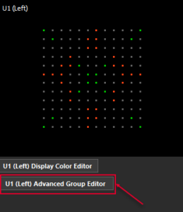 A new button, Advanced Group Editor, has been added to the MCP Auto Connection window. This button opens the Advanced Group Editor form where you can edit pin groups after importing a PLOC file.
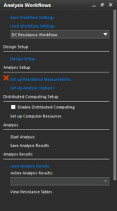 A new workflow, DC Resistance, is available in the Analysis Workflows of Sigrity Aurora. This workflow computes the DC resistance for specific power and ground nets present in a design. Use this workflow to compute partial resistance or loop resistance for lumped-to-lumped or multiple-to-multiple measurement models. The analysis results of this workflow are displayed in resistance tables that show the measured partial and loop resistances along with a pass or fail status.
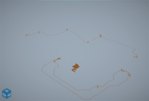 A new 3D canvas, Allegro 3DX Canvas, is available in the Interconnect Model Extraction and Topology Extraction workflows for displaying and analyzing 3D net geometries. The new 3DX canvas displays the 3D preview prominently, minimizing surrounding options and controls to create a clutter-free viewing experience.
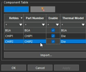 The Thermal Workflow now includes multi-die support.
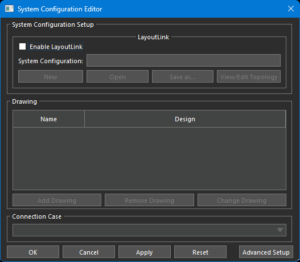 The Topology Extraction Workflow now supports topology-driven LayoutLink setup to provide the multi-layout SI simulations capability from the layout itself.
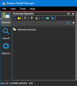 Analysis Model Manager includes an option to activate an improved user interface, aimed at supporting an enterprise-level signal integrity library implementation.
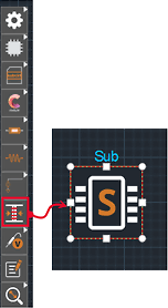 A hierarchical structure can be created with a new subsystem block for topology simplification and design reuse. This new block is available in Topology Explorer, Serial Link Analysis (SLA), Parallel Bus Analysis (PBA), SystemPI (DC IR Drop Analysis, PDN Impedance Analysis, and Power Ripple Analysis).
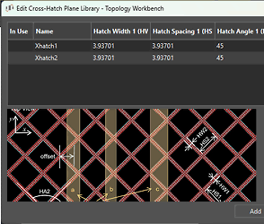 The Trace Editor includes the Edit Cross-Hatch Plane Library button to model traces over cross-hatch planes. This feature helps evaluate transmission line propagation constants and impedance during the pre-layout stage of rigid-flex design, ensuring optimal performance.
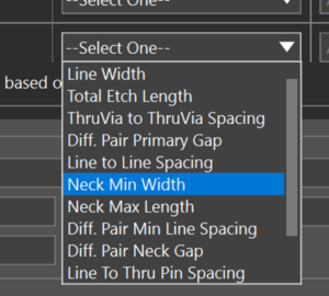 For Layout and Clarity3D blocks, optimized parameters from Sweep Manager or Optimality can be written to a constraint file and backannotated to the Allegro X Constraint Manager.
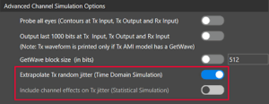 All Tx jitter present in an AMI model or the Analysis Options panel can be included in the post-processing of the jitter distribution collected over the duration of the simulation.
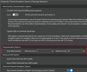 The Characterization Options section of the Options form allows the minimum and maximum time for automatic detection of the steady state for characterization waveforms can be defined. The circuit simulation stops after the steady state has been reached.
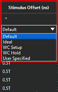 With the Statistical Simulation option selected in the Channel Simulation tab of the Analysis Options panel, the IO Models and Stimulus tab allows for a stimulus offset for statistical simulations.
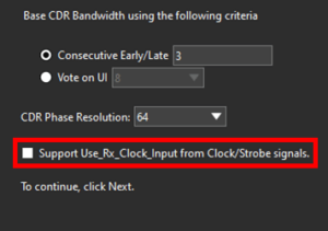 In the Parallel Bus Analysis workflow, the AMI Builder Wizard allows the creation of AMI models that support Use_Rx_Clock_Input from clock or strobe signals.
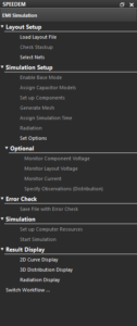 The Electromagnetic Interference Simulation workflow can be accessed through the properties of the FDTD-D (Finite Difference Time Domain) block.
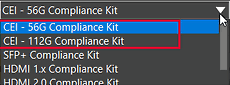 The following new compliance kits are available in release 25.1.
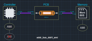 New templates have been added to the Parallel Bus Analysis workflow for DDR5 and LPDDR5/5X.
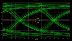 The StressedDiamond option is now available in the Mask list in the Measurement Customization window. This option can be used to review stressed eye measurements from the generated measurement report in the Parallel Bus Analysis workflow.
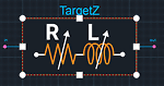 A new Target Impedance block has been added to set the resistance and inductance ranges. Only one Target Impedance block can be added to a canvas, and the other blocks on the canvas must be included in its netlist.
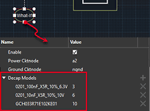 Multiple instances of decap models can be assigned to a single what-if block for sweeping. In the Sweep Manager, a single instance of multiple decap models can be swept.
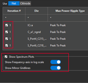 The Generate Report dialog box now has checkboxes to select specific simulation results to include in the report. Additionally, options are available to include frequency spectrum plots with plotting options to show the frequency axis in the log scale and minor gridlines.
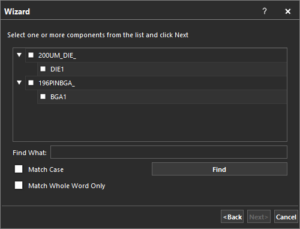 The search functionality in the Set up VRMs, Set up Sinks, and Set up Discretes wizards has been improved to efficiently search for components by name. The Up and Down radio buttons have been removed to provide a simple and effective component search.
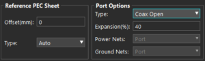 The following enhancements have been made to the Component Geometry Model Editor:
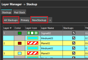 The following improvements have been made in the Stackup window for rigid-flex designs in Clarity 3D Layout:
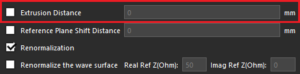 A new option, Extrusion Distance, has been added to the Port dialog box for wave ports. This feature extends all geometry and boundary conditions that intersect the wave surface and repositions the wave port to the end of the extended geometry. The extrusion vector is oriented perpendicular to the wave surface and directed away from the propagation path. This enhancement enables more accurate mode excitation and improves the precision of S-parameter calculations.
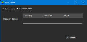 The Target File Editor dialog box has been renamed to Spec Editor. It now includes options to specify target values for frequency domain, time domain, and S-parameter results.
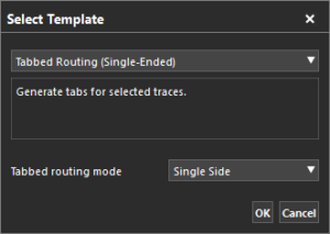 A new template, Tabbed Routing (Single Ended), is now available in Clarity 3D Layout. This template can be used to add trapezoidal shapes (tabs) to one or more parallel or non-parallel traces. This helps manage the impedance in the pin field/breakout regions and minimize crosstalk in the open field regions by optimizing the trace geometry.
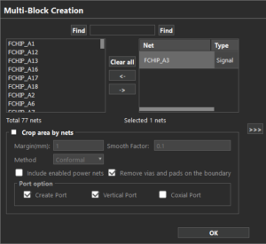 The Intelligent Multi-Block Extraction workflow has been enhanced with support for multi-block files in the MBTX format and updates to the MCM flow.
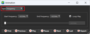 Frequency-based animation has been added for the Real and Imaginary parts of the field quantities. This option allows you to visualize the field behavior across selected frequencies for improved analysis.
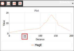 Several improvements have been introduced to the near and far field analysis capabilities in Clarity 3D Layout and Clarity 3D Workbench including toggling between linear and log scales, point markers, line markers, creation of dynamic phase animations, probe points and more.
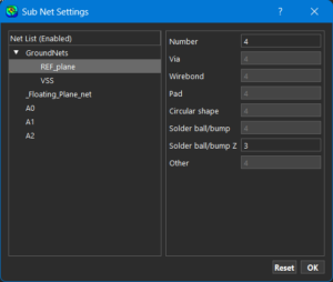 Advanced Net Settings has been added to the Geometry tab of the Options dialog box. This button opens the Sub Net Settings dialog box which allows the setting of a different value for vias, pads, solder balls, and more, based on the enabled nets. This reduces the time required for meshing.
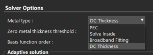 The Metal Type Settings have been enhanced to offer more control over the simulation accuracy and performance:
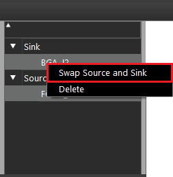 A new option, Swap Source and Sink, has been added to the context menu in the Inductance Extraction workflow. This feature can be used to quickly fix incorrect source or sink assignments without reassigning them manually.
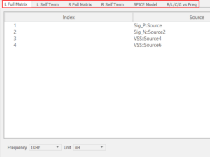 Simulation results, including L Full Matrix, L Self Term, and SPICE Model are accessible through their respective tabs.
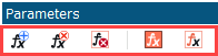 The Parameters panel in Clarity 3D Workbench now includes a toolbar for ease of use.
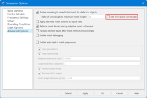 A new option, Use Free Space Wavelength, has been added to the Advanced Options tab of the Simulation Options dialog box. This option ensures the initial mesh sizing is computed using the wavelength in free space at the solution frequency, providing a consistent baseline for meshing dielectric structures.
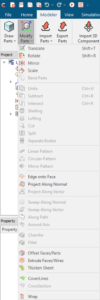 Additional commands have been added to the Modeler tab in Clarity 3D Workbench to thicken sheets, examine cross-sections, draw cables, and more.
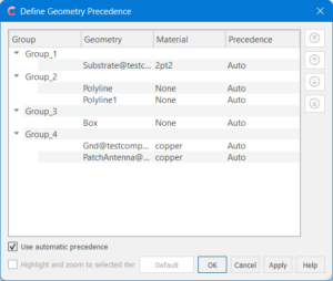 A new button, Define Geometry Precedence, has been added to the Simulation tab. This feature can be used to control how overlapping geometries are rendered by assigning object properties. This can be used for more accurate meshing results, especially in complex models where geometry intersections may affect simulation accuracy.
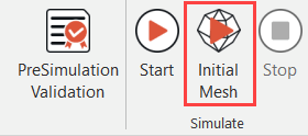 A new button, Initial Mesh, has been added to the Simulation tab. This option enables early detection of design issues and accelerates the simulation setup process, saving time.
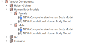 Highly detailed and anatomically accurate human body models based on medical data from the US Library of Medicine’s Visible Human project are now available. Available models include:
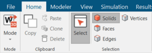 Clarity 3D Workbench now features a redesigned user interface built around a modern ribbon layout, offering a structured and streamlined way to access key features. By replacing the traditional drop-down menus, the new ribbon layout organizes commands and options into tabs and groups, ensuring frequently-used commands are readily available and logically categorized.
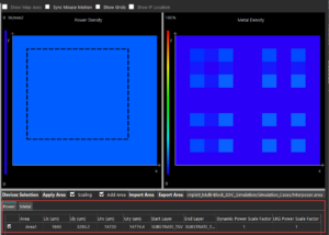 While previewing the power distribution in the Component Model viewer in Celsius Layout and Celsius 3DIC, you can now configure scale factors for power and metal independently through their respective tabs. This separation provides a more organized interface for managing scaling parameters.
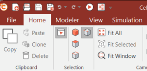 Celsius 3D Workbench now features a redesigned user interface built around a modern ribbon layout, offering a structured and streamlined way to access key features. By replacing the traditional drop-down menus, the new ribbon layout organizes commands and options into tabs and groups, ensuring that frequently-used commands are readily available and logically categorized. With the categorized tabs, contextual controls, and updated labels, the Ribbon UI provides a more intuitive, task-focused workflow that boosts productivity for experienced users while reducing the learning curve for new users.
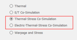 Two new co-simulation options are available for transient analysis, enabling more integrated and accurate Multiphysics modeling:
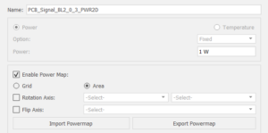 Polygon shapes and transient power profiles can now be used for greater flexibility in thermal modeling when defining heat sources in Celsius 3D Workbench. You can now define the area of a heat source using polygon shapes and set up a transient power profile to model time-dependent power behavior.
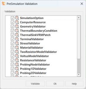 Designs can now be validated before running a simulation with the new Pre-Simulation Validation feature. This helps identify potential issues before the simulation is run, saving time and improving simulation reliability.
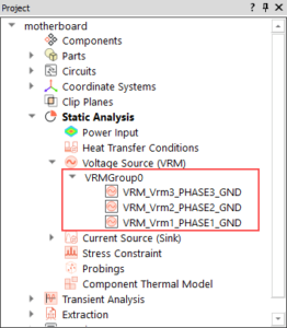 When importing an SPD file created in Celsius Layout, Celsius 3D Workbench automatically identifies each VRM phase of a multi-phase VRM and imports them as individual VRM objects. Phases with matching nominal and sense voltages are grouped into a single VRMGroup, reducing manual setup effort and ensuring accurate power modeling.
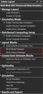 Celsius 3DIC workflow now supports a model-based approach that enables direct creation and instantiation of reusable design entities. This refined flow, with the Block Model Manager and Block Instance Manager, simplifies setup and enhances design efficiency, particularly when working with complex multi-die systems. Models can be added, instantiated, and connected within a more intuitive and cohesive environment.
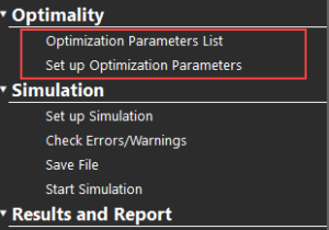 Celsius 3DIC now supports the Optimality Intelligent System Explorer. Optimality uses AI-driven multidisciplinary analysis and optimization (MDAO) technology to optimize designs quickly and efficiently without compromising on accuracy.
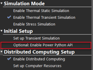 Celsius 3DIC now includes support for the Python Power API model, allowing you to implement active power and thermal control strategies with Python scrips. With the Power Python model, you can write and test Python scripts that monitor device templates and apply dynamic power switching strategies. This includes invoking thermal throttling to prevent overheating during high workloads or implementing advanced control mechanisms, such as multi-control and Proportional Integral Derivative (PID) control, that maintain the system in a stable, predictive state by continuously switching power maps between real-time feedback.
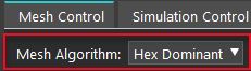 Hex Dominant is now available as a meshing algorithm in Celsius 3DIC, enabling structure hexahedral meshing for improved simulation accuracy and convergence. To use this feature, ensure ANSA EBTA CAE is installed and license on your machine.
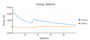 AI models are a new modeling level for IT Equipment in both Reality DC and Celsius EC Solver. In Celsius EC Solver, the IT equipment can be trained with CFD simulation data from a detailed server model, obtained over multiple scenarios with varying operating conditions. This equipment can then be added to a Reality DC model. The trained model can produce predictions that capture the behavior of IT at a range of operating conditions. AI modeling is available for both air and hybrid-cooled servers and compatible with all coolant connection types available in the software.
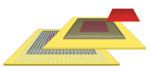 The new Bump Object in Celsius EC Solver can be used to fully represent solder bumps and balls on a PCB, allowing for greater modeling accuracy of intricate package components.
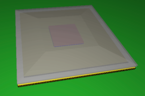 The new Lid Object in Celsius EC Solver can be used to represent the conductive cover of a flip-chip component package, allowing for more customizable geometry on your package designs.
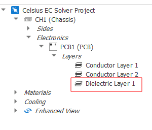 Dielectric layer objects, previously modeled as part of existing PCB models, can now be modeled as separate objects. This allows for more accurate modeling of electric conductivity across the PCB.
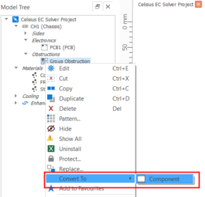 Group Obstructions can now be converted to Detailed Components. Components defined in MCAD files can easily be imported into the model. The conversion process attempts to preserve the structural hierarchy of the objects inside the group obstruction.
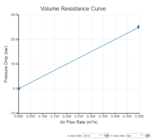 Bar units can now be used for defining pressures in property sheets, curves, push pins, and legends.
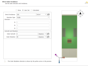 The position of the sun can now be specified with solar angles; solar azimuth and solar elevation, rather than unit vectors.
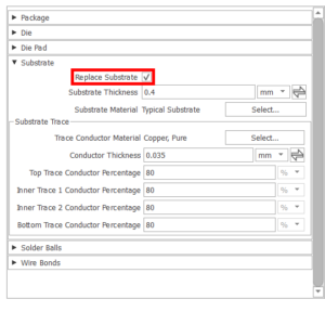 The new Replace Substrate checkbox in the package builder allows the choice between retaining a component’s existing substrate or replacing it with a new one. This allows the parts around the existing substrate to be defined.
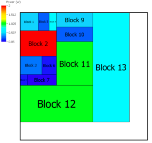 Names are now displayed on the blocks of a power map and in the power map table for the Defined Power Blocks configuration. This allows for better visualization and definition of the power distribution across an object.
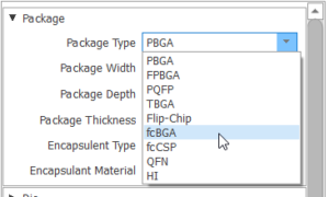 Three new package builder types have been added: fcBGA, fcCSP, and HI. This makes it easier to quickly create new components with desired parts such as lids, bumps, and encapsulant automatically added to the component model.
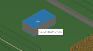 A new tool has been added to select the sides of a solid obstruction on which to add to a face object, eliminating the need to add all faces and manually remove faces that are not needed.
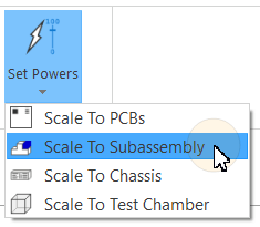 Subassemblies are now included in the list of objects to scale powers to, allowing for greater power draw accuracy in the model.
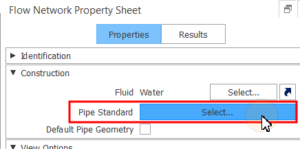 The thickness and diameter properties of flow network pipes can now be inferred directly from pipe standard data sheets, such as those published by ASME. This provides a more streamlined modeling process for your flow network pipes, adhering to the geometry standards set out in the data sheets.
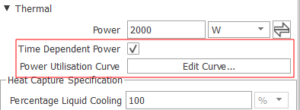 New properties related to time-dependent power have been added to the IT Equipment property sheet. This allows for transient analysis of power on IT equipment modeled as part of a flow network without having to rely on a 3D model.
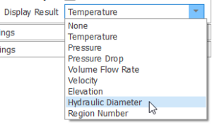 The Display Result options have been expanded to include a new variable, Hydraulic Diameter. This plot makes it easier to comparatively visualize circular and rectangular pipes/ducts.
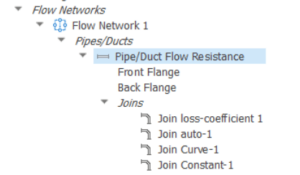 The modeling process for valves and joins on pipes and ducts has been simplified by introducing the option to define them and their associated properties on the same property sheet as the parent pipe/duct. This includes the ability to specify the characteristics of valves and their opening position. The fittings no longer have to be explicitly modeled in the flow network. However, their properties will still be accounted for and they will still appear in the Model Tree. This allows for easier modeling and definition of joins and valves, particularly if the latter are not fully open.
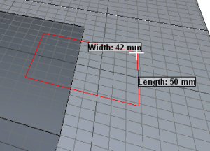 CAD parts can now be created directly in Celsius EC Solver. To do this, sketch them directly to a Sketch Plane object, which can now be added to the top-level project object.
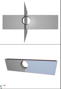 It is now possible to split a CAD solid into two using a Sketch Plane and the new Split tool. Objects can easily be separated from a single solid and edited individually.
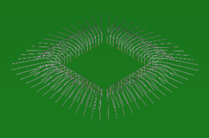 Electrical connections made using wire bonding are now supported when importing ECAD files as components into the software.
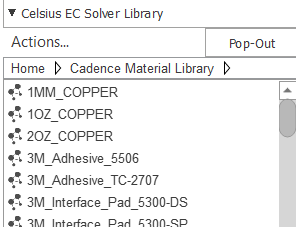 The material library used in other Sigrity products is now automatically imported into Celsius EC Solver as a separate library in the object panel.
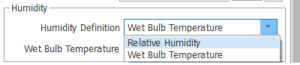 Humidity calculations have been added to the Solution Control options in Celsius EC Solver and new options to specify boundary conditions on Vents and Environments have been added. The available humidity configurations for these objects include Relative Humidity, Wet Bulb Temperature, and Moisture Content.
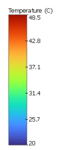 The size and shape of max/min markers on result planes can now be customized, enhancing result visualization for areas of high or low solution field values, such as temperature.
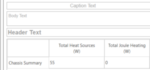 The Report functionality has been redesigned and enhanced to make it easier to create highly-customizable reports for Celsius models. Report text, images, and graphs can now be edited directly from within the Report Document view. Updates have also been made to the template functionality, the export options, and the customization of the look of the report (such as fonts and legends).
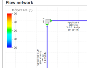 Network view objects can now be added to a report, allowing for greater coverage of model aspects. Currently-supported views include Flow Networks and Control Networks.
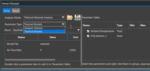 The Celsius Thermal Network workflow now integrates a Sweep Manager. The Sweep Manager can be used to set up and sweep different values of key parameters, such as power values and map files, heat transfer coefficient (HTC) values and map files, and inlet fluid temperatures and flow rates. This integration streamlines the process of analyzing and optimizing the thermal network performance, saving users time and effort.