Rigid-flex designs contain multiple zones to accommodate the differing stackups for rigid and flex areas of the PCB. Due to the different stackups, materials, and manufacturing capabilities each area often requires different design rules. OrCAD X Presto includes the ability to quickly and easily create region-based rules for rigid flex designs, allowing engineers to define and assign specific rules to different sections of the board.
This quick how-to will provide step-by-step instructions on how to create region-based rules for rigid flex designs in OrCAD X Presto.
To follow along, download the provided files above the table of contents.
How-To Video
 Open in New Window
Create Region-Based Rules for Rigid Flex Designs
Step 1: Open the provided design in OrCAD X Presto 24.1.
Step 2: Before a constraint set can be assigned to any region on the board, a constraint region rule set must be created. Select Tools > Constraint Manager from the menu.
Step 3: The Constraint Manager window opens. Select the Physical domain from the Worksheet Selector.
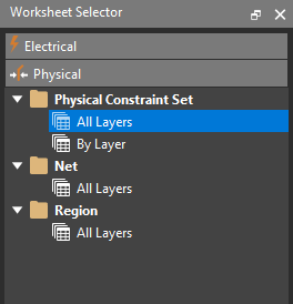
Step 4: Select the Physical Constraint Set > All Layers worksheet.
Step 5: Right-click the row for the Default constraint set and select Create > Physical CSet.
Step 6: The Create Physical CSet window opens. Name the set FLEX_WIDE and click OK.
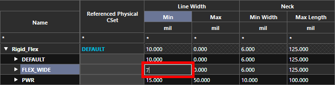
Step 7: The FLEX_WIDE constraint set is added to the table. Double-click the cell for Minimum Line Width and enter 7 to reduce the minimum line width inside the flex zones.
Create a Constraint Region
Step 8: A special constraint region must be created before a CSet can be assigned to any defined zones. Select the Region > All Layers worksheet from the Physical domain.
Step 9: Right-click in the table and select Create > Region.
Step 10: The Create Region window opens. Enter FLEX_WIDE for the name and click OK.
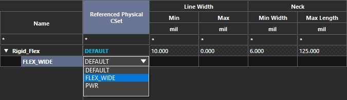
Step 11: Double-click the cell for Referenced Physical CSet. Select the FLEX_WIDE CSet from the dropdown to assign it to the new region. The rules defined in the CSet are assigned.
Close the Constraint Manager.
Assign Region-Based Rules for Rigid Flex Designs
Step 12: With the constraint set and region defined, they must be assigned to a zone on the board to have any effect. Select the flex zone FLEX_DISP on the PCB canvas.
Note: Learn how to define zones for rigid-flex designs here.
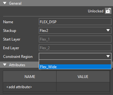
Step 13: The Properties panel populates with shape and zone properties. Choose the created Flex_Wide region from the Constraint Region drop-down menu. The Flex_Wide constraint set is applied to this rigid flex zone.
Step 14: Click anywhere in the canvas to deselect the zone.
Verifying Region-Based Rules for Rigid Flex Designs

Step 15: To confirm that the physical constraints take effect inside the constraint region, select the Add Connect mode from the toolbar.

Step 16: On the main controller section of the board, select the pin for net A_2 on the top IC to start routing.
Step 17: Route to the edge of the rigid flex. Double-click to create a via.
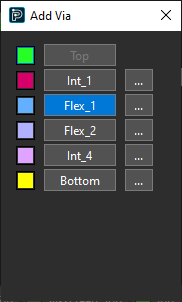
Step 18: The trace cannot be routed on the rigid flex itself because the TOP subclass does not exist in the rigid flex. Select Flex_1 in the Add Via window. The via is created and the layer changes to FLEX_1.
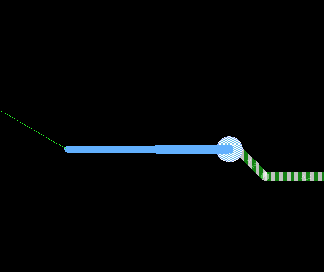
Step 19: With the trace attached, hover your cursor over the rigid flex zone. The trace thins inside this zone to match the region constraint.
Step 20: Select Arc for the Trace Type in the Add Connect widget for smoother routing inside the rigid flex zone.
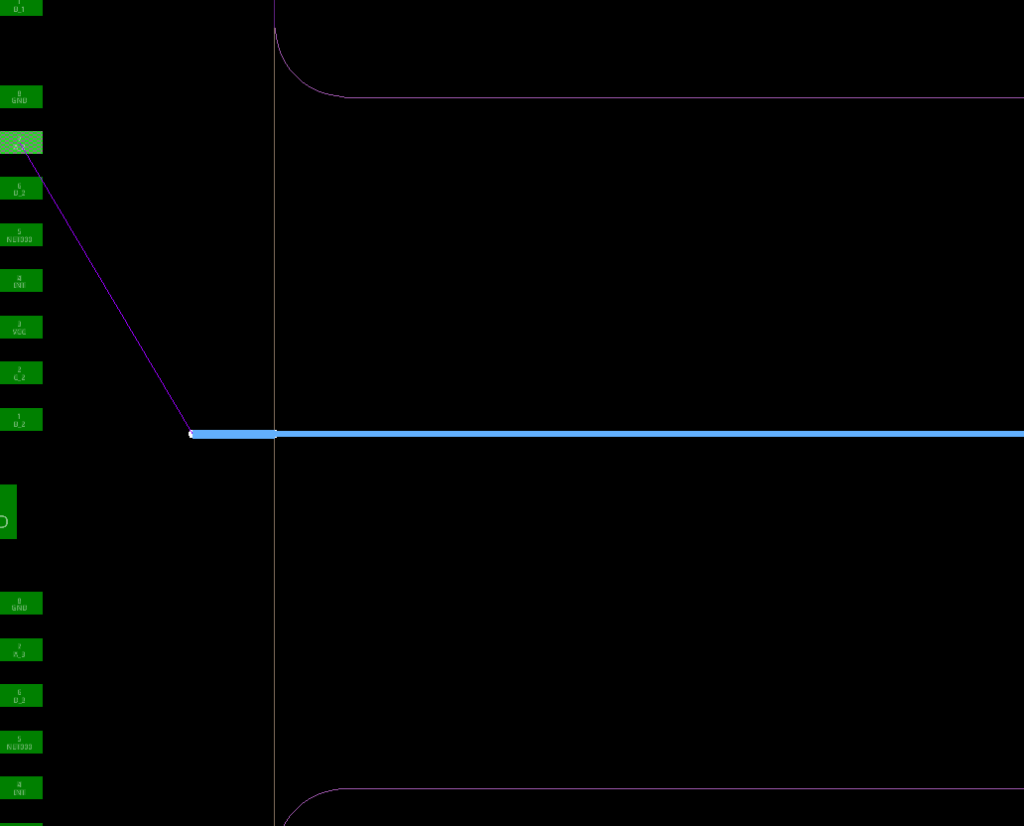
Step 21: Route the trace to the other side of the flex zone. When leaving the zone, the original trace thickness is restored.
Step 22: Double-click to create a via and select Top from the Create Via window.
Step 23: Select Line for the Trace Type to return to the normal sharp angle mode.
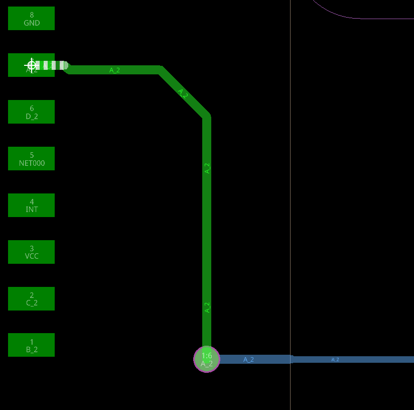
Step 24: Route the trace to the A_2 pin on the display. The trace is 7mil wide in the rigid flex zone and 10mil wide outside of it.
Wrap Up & Next Steps
Quickly create region-based rules for rigid flex designs to adhere to the different requirements for flex and rigid sections of the PCB with OrCAD X Presto 24.1. Test this feature and more with a free trial of OrCAD. Want to learn more about OrCAD X Presto? Check out our other how-tos and step-by-step walk-throughs at EMA Academy.

