Before a PCB is put into production, performing SPICE simulations can make the difference between a pre-production revision and a costly board respin. Simulations, such as a bias point simulation, are essential to analyze potential faults, undesired circuit behavior, and even component failures. A bias point simulation shows the steady-state voltage, current, and power directly on the schematic allowing you to quickly verify the basic functionality of a circuit. With PSpice, you can efficiently perform a bias point simulation on your circuits directly within your OrCAD Capture schematic to:
- Identify undesirable behavior
- Ensure circuit stability
- Estimate power consumption
- Ensure power efficiency
- Verify accuracy of component values
- Optimize circuit for specific performance criteria
- Guarantee reliability
This quick how-to will provide step-by-step instructions on how to perform a bias point simulation in OrCAD PSpice.
To follow along, download the provided files above the table of contents.
How-To Video
 Open in New Window
Creating a Simulation Profile
Step 1: Open the provided design in OrCAD PSpice Designer.
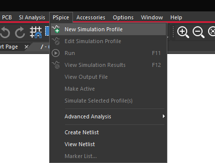
Step 2: Select PSpice > New Simulation Profile from the menu.
Step 3: Name the simulation profile Bias_Point and click Create.
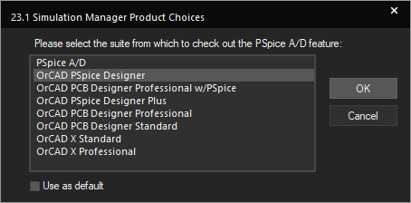
Note: If the Simulation Manager Product Choices window opens, select the appropriate license and click OK.
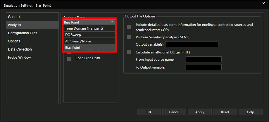
Step 4: Select Bias Point from the Analysis Type drop-down menu.
Note: PSpice contains additional simulation options to perform Time-Domain or transient analysis, DC Sweep analysis, AC Sweep analysis and noise analysis. To learn how to perform these analyses, view more PSpice how-tos at EMA Academy.
Step 5: Leave the other settings as the defaults and click OK.
Running a Bias Point Simulation
Step 6: Select PSpice > Run from the menu or the Run button on the toolbar to start the simulation.
Step 7: The PSpice A/D window will open but not show a plot. Close the window.
Note: Bias point results are displayed directly in the schematic, so running a bias point simulation will show nothing in the plot window.
Viewing Simulation Results
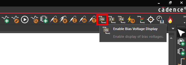
Step 8: Select the Enable Bias Voltage Display button from the toolbar.
Note: This can also be activated by selecting PSpice > Bias Points > Enable Bias Voltage Display.
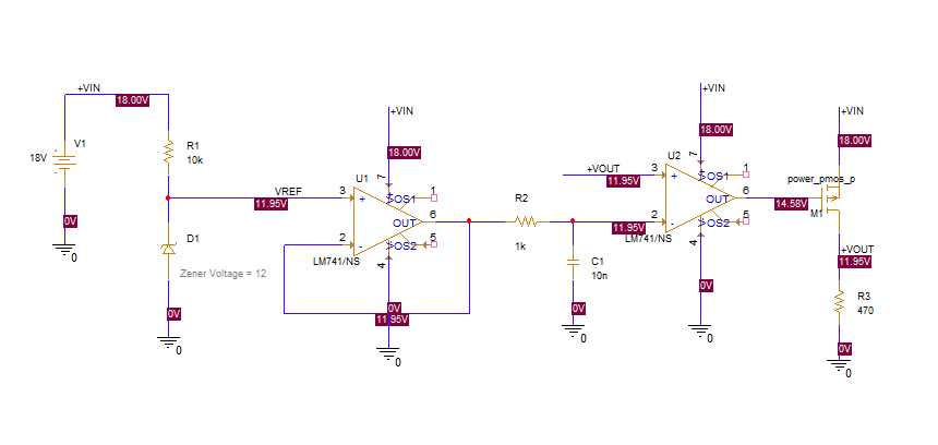
Step 9: View the bias point result voltages at each net in the schematic.
Step 10: Select the Enable Bias Voltage Display button to toggle the voltage display off.
Step 11: Select Enable Bias Current Display button from the toolbar.
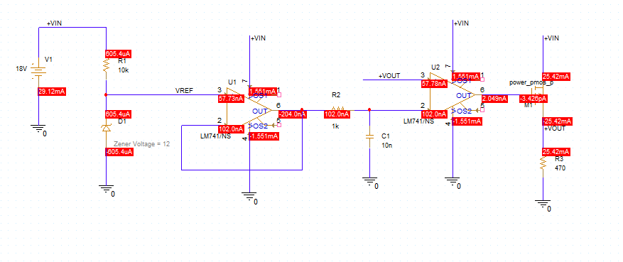
Step 12: View the bias point result currents for each component.
Note: Current bias point values are displayed on the component pins.
Step 13: Select the Enable Bias Current Display button to toggle the current display off.
Step 14: Select Enable Bias Power Display button from the toolbar.
Note: This can also be activated by selecting PSpice > Bias Points > Enable Bias Power Display.
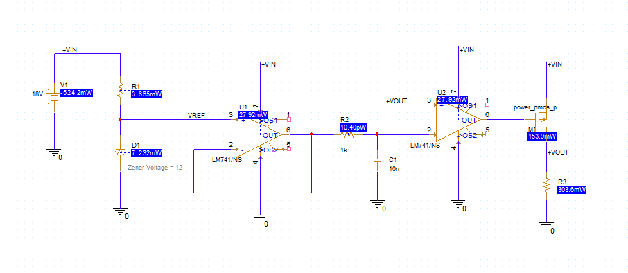
Step 15: View the bias point results. The power dissipated (positive) or supplied (negative) by each component is shown in the schematic.
Step 16: Select Enable Bias Power Display button to toggle the power display off.
Wrap Up & Next Steps
Perform a bias point simulation to view steady-state component parameters and analyze circuit functionality in PSpice. Test out this feature and more with a free trial of OrCAD. Want to learn more about PSpice? Get access to free how-tos, courses, and walk-throughs at EMA Academy.
