Before a PCB is put into production, performing SPICE simulations can make the difference between a pre-production revision and a costly board respin. Simulations, such as transient simulations, are essential to analyze potential faults, undesired circuit behavior, and even component failures. A transient simulation shows the behavior of voltage, current, or power in the time-domain as if it was plotted on an oscilloscope. With PSpice, you can efficiently perform a transient simulation on your circuits directly within your OrCAD Capture schematic to:
- Analyze circuit behavior with respect to time
- Analyze circuit startup
- Analyze circuit shutdown
- Identify potential issues in circuit behavior
- Verify circuit functionality and performance
This quick how-to will provide step-by-step instructions on how to perform a transient simulation in OrCAD PSpice.
To follow along, download the provided materials above the table of contents.
How-To Video
 Open in New Window
Creating a Transient Simulation Profile
Step 1: Open the provided design in OrCAD PSpice Designer.
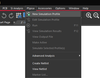
Step 2: Select PSpice > New Simulation Profile from the menu.
Step 3: Name the simulation profile TRANS and click Create.
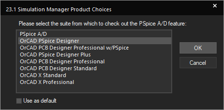
Note: If the Simulation Manager Product Choices window opens, select the appropriate license and click OK.
Step 4: Select Transient from the Analysis Type drop-down menu.
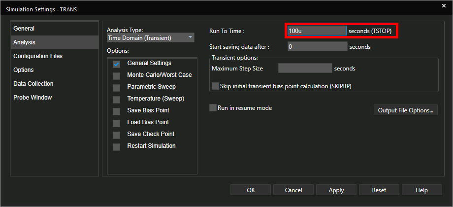
Step 5: Enter 100u for the Run To Time. This will run the simulation for 100usec.
Step 6: Leave the other settings as the defaults and click OK.
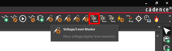
Step 7: Select the Voltage/Level Marker button from the toolbar.
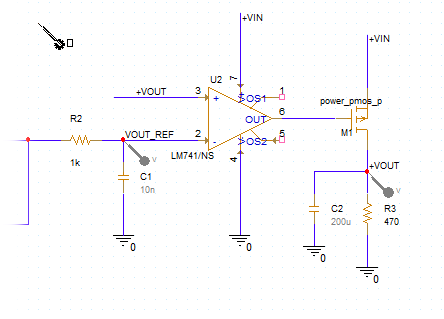
Step 8: Click to place probes on the +VOUT and VOUT_REF nets. Right-click and select End Mode when finished.
Performing a Transient Simulation
Step 9: Select PSpice > Run from the menu or the Run button on the toolbar to start the simulation.
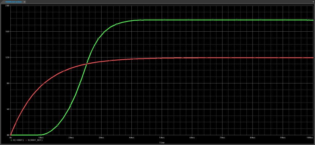
Step 10: The PSpice A/D window opens. View the simulation results. The output reference rises as expected. The output overshoots and starts decaying.
Step 11: Minimize, but do not close the PSpice A/D window.
Note: Alternatively, if your system has multiple monitors, move the window to another monitor to keep it in view.
Adding Current Probes
Step 12: Back in the schematic, select the Current Marker button from the toolbar.
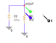
Step 13: Click to place a current marker at the input of resistor R3. Right-click and select End Mode when finished.
Step 14: View the PSpice A/D window. A new trace showing resistor current is visible.
Note: Due to the comparatively low current of the resistor, the scale is off for the three plotted traces. We will correct this in the next section.
Adding a Y Axis
Step 15: Select Plot > Add Y Axis from the menu.
Step 16: A new Y axis is added to the design. Select -I(R3) in the legend and press CTRL-X on the keyboard to cut.
Step 17: With the new Y axis selected, press CTRL-V to paste.
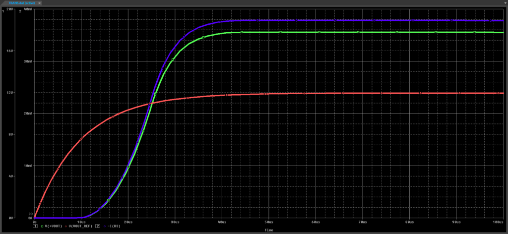
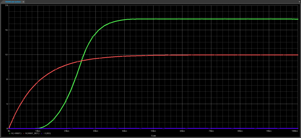
Step 18: View the results. The current rises proportionally to the voltage and the new Y axis is populated with current values.
Wrap Up & Next Steps
Perform a transient simulation to analyze circuit behavior in the time-domain and verify proper functionality before production with PSpice. Test out this feature and more with a free trial of OrCAD. Want to learn more about PSpice? Get access to free how-tos, courses, and walk-throughs at EMA Academy.

