With today’s designs getting physically smaller and electronically more complex, good communication with the mechanical engineering team is critical. To ensure component fit and placement within the mechanical housing, analysis with 3D models should be performed early in the design process to guarantee a successful assembly and eliminate costly respins; however this communication is often difficult due to the varying software used for MCAD and ECAD design. Seamlessly collaborate between MCAD and ECAD teams with bi-directional integration between Allegro X and SOLIDWORKS with MCADx.
This quick how-to will provide step-by-step instructions on how to efficiently collaborate with your mechanical engineer with MCADx in Allegro X Artist.
How-To Video
 Open in New Window
Creating a Board in SOLIDWORKS
Note: For the purpose of this how-to, we will create a mechanical board design in SOLIDWORKS and import it into Allegro.
Step 1: Open Allegro X Artist and create a new, blank board design. Ensure a schematic is synced and imported so components can be placed.
Step 2: Open SOLIDWORKS and select File > New from the menu.
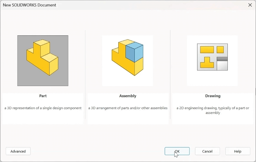
Step 3: Select Part in the New SOLIDWORKS Document window and click OK.
Step 4: Select File > MCADx. Here you can:
- Import a PCB Design
- Export a PCB Design
- Customize the Workflow
- Set MCADx Preferences such as File Paths
Step 5: Select Preferences. Configure the correct paths for Library Parts and Collaboration Folder. Click OK.
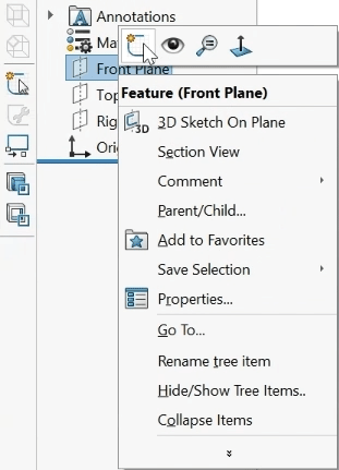
Step 6: In the Front Plane option for the new part, right-click and select Sketch.
Step 7: Select the Rectangle option.
Step 8: Click to start drawing a rectangle at the origin and click again to finish.
Step 9: Select Smart Dimension from the toolbar.
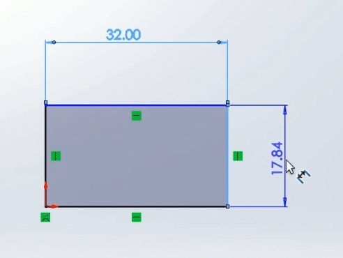
Step 10: Click to create dimensions for the board width and height and click again to place.
Note: Double-click the dimension to change the value as needed.
Step 11: Select Exit Sketch to end the sketch mode.
Step 12: Select Extruded Boss/Base from the toolbar to extrude the board.
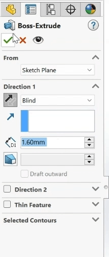
Step 13: Select the option to mirror the extrusion and set the distance to 1.6mm. Click the checkmark to create the extrusion.
Step 14: Select File > Save from the menu.
Step 15: Enter a name for the board file, browse to the desired location, and click Save.
Assigning a PCB Outline
Note: PCB part functions must be defined in SOLIDWORKS to collaborate with Allegro.
Step 16: Select Tools > PCB Tools [Part] > Assign PCB Outline from the menu.
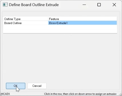
Step 17: A window opens to define the board outline. Select Boss-Extrude1 from the outline list and click OK.
Step 18: You will be prompted to create a board outline assembly. Click Yes.
Step 19: The board assembly is generated. A prompt will appear when generation is finished. Click OK. The part now has a top, dielectric, and bottom.
Step 20: Select File > Make Assembly from Assembly from the menu.
Note: This must be done before the component can be placed.
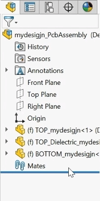
Step 21: To make the origin visible, select View > Hide/Show > Origins.
Step 22: Select the origin to place the board assembly.
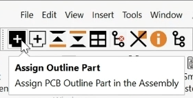
Step 23: Select Assign Outline Part to assign the part as the assembly outline.
Step 24: A window appears to select the board outline part. Click OK to automatically select the drawn outline and close the window.
Placing a Part in SOLIDWORKS
Note: Some critical parts may need to be placed by the mechanical engineer to ensure proper fit and integration into the mechanical housing.
Step 25: Select Place Top Part from the toolbar to place a top part.
Step 26: Select the desired part from the SOLIDWORKS part library and click Open. The part is placed on top of the board automatically.
Step 27: Select Mate from the toolbar to align the component further.
Step 28: Use the Mate tool to place the component in the correct location. In this example, making the component faces flush with the board edges and adjusting the spacing.
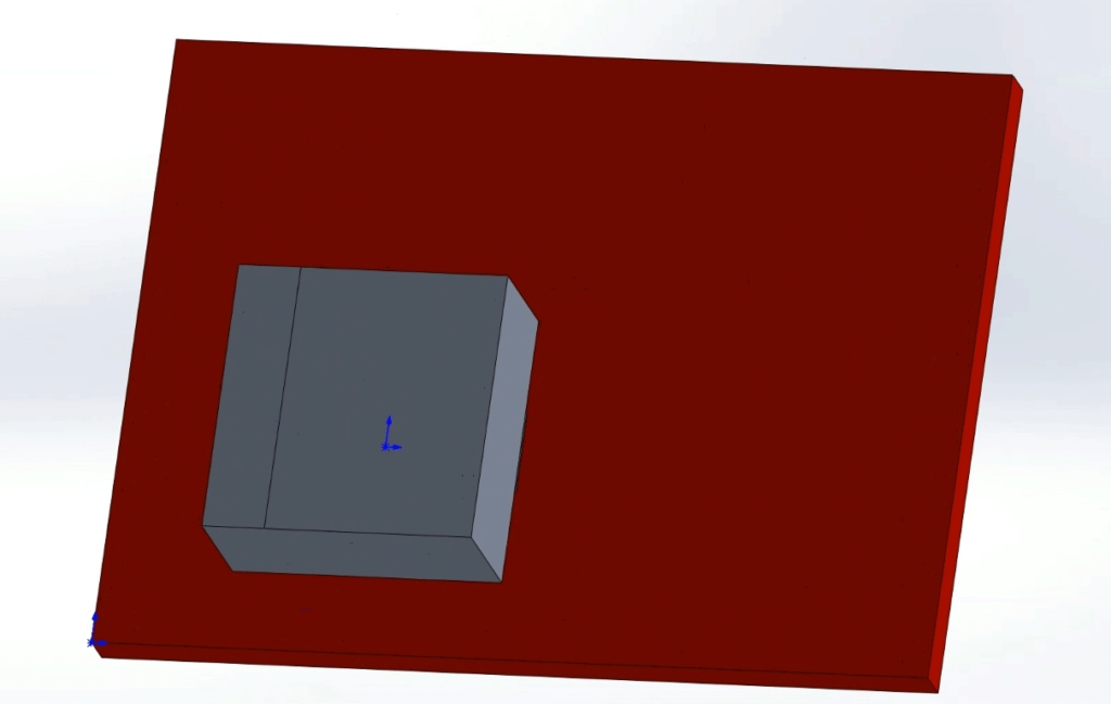
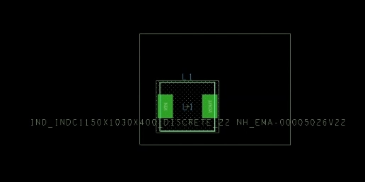
Step 29: View the results. The component has been placed and aligned.
Step 30: Click the checkmark to exit Mate mode.
Assigning Part Data
Note: The part’s reference designator must be linked in SOLIDWORKS for collaboration with Allegro X.
Step 31: Select Assign Part Data from the toolbar.
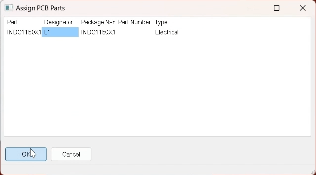
Step 32: The Assign PCB Parts window opens. Enter the designator into the Designator field and click OK.
Step 33: Select File > Save from the menu.
Step 34: Save the assembly in the same location as the board file.
Exporting the Board Outline
Step 35: Select Export from the toolbar.
Step 36: The MCADx Export window opens. Select the ellipsis to browse for a location to save the file.
Step 37: Navigate to the designated collaboration folder to save the MCADX file. Enter a name for the file and click Save.
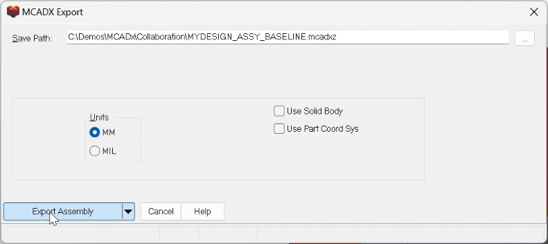
Step 38: Select Export Assembly. A prompt will appear when the export is complete. Click OK.
Importing the MCADx File
Step 39: Open the blank design in Allegro X Artist or any Allegro X license.
Step 40: Select File > Import > MCADx from the menu.
Step 41: The MCADX In window opens. Select the ellipsis to browse for the file.
Step 42: Browse to the location of the saved assembly file, select it, and click Open.
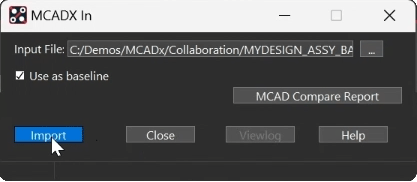
Step 43: Click Import to import the assembly.
Step 44: The Flow Manager Import window opens. Check the desired options to import the board outline and components.
Note: A prompt will appear that the board thicknesses are different between the two designs. Click OK.
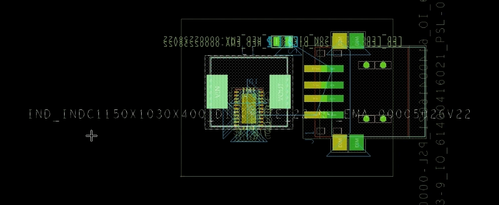
Step 45: Click OK. The board outline and placed component are imported.
Step 46: Click Close in the MCADx in window.
Placing Additional Components
Step 47: Select Place > Components Manually from the menu.
Step 48: Check the options for the components to place.
Step 49: Click to place the components on the board.
Note: Right-click and select Mirror to place the component on the other side of the board. Right-click and select Rotate to rotate the component. Click Hide to hide the placement window if needed.
Step 50: When finished, select File > Save from the menu.
Collaborate Between MCAD and ECAD
Step 51: Select Tools > MCADX Collaboration from the menu.
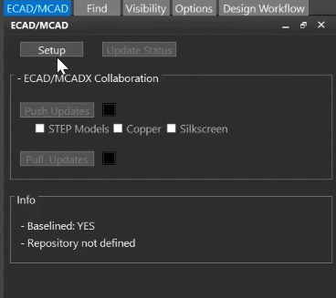
Step 52: The ECAD/MCAD panel opens. Select Setup.
Step 53: Select the ellipsis for the File Repository Location. Browse to the location of the collaboration folder and select Choose.
Step 54: Select Filter Options to choose which objects to sync.
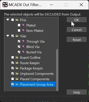
Step 55: Check the following options to exclude them from the output:
- Package Keepout
- Route Keepout
- Via Keepout
- Vias
- Route Keepin
- Package Keepin
- Placement Group Area
Step 56: Click OK and click OK in the Collaboration Setup window.
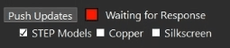
Step 57: In the ECAD/MCAD panel, check the option for STEP Models under Push Updates.
Note: Options for Copper and Silkscreen are also available.
Step 58: Select Push Updates.
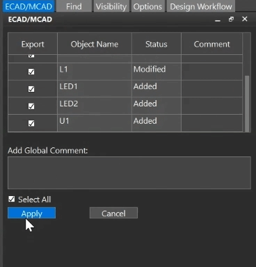
Step 59: A table of updates is visible in the ECAD/MCAD panel. Select Apply to push the changes.
Step 60: A prompt appears that the mapping file was generated. Click OK.
Step 61: Return to the ECAD/MCAD panel. The status of Push Updates is now “Waiting for Response.”
Syncing Changes in SOLIDWORKS
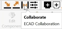
Step 62: Reopen SOLIDWORKS and select the Collaborate button from the toolbar.
Note: If you exported the ECAD/MCAD file into a different location that the board model, you may be prompted that the current document folder does not match. Click OK.
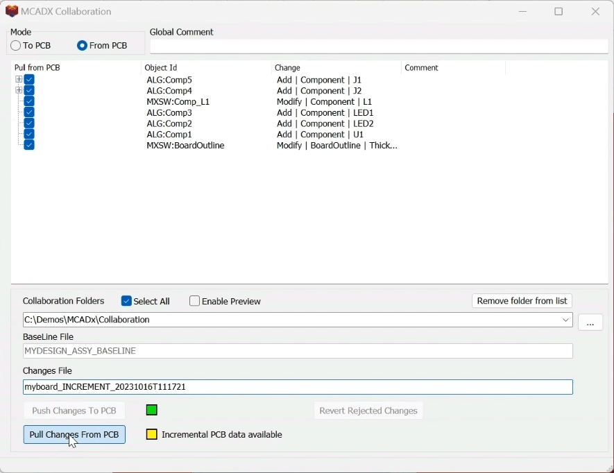
Step 63: The MCADX Collaboration window opens, showing any changes made. Check Select All and click Pull Changes from PCB.
Step 64: The Pull Changes from PCB indicator turns to green. Close the MCADX Collaboration window.
Note: Select File > Close to close the original board assembly files as needed.
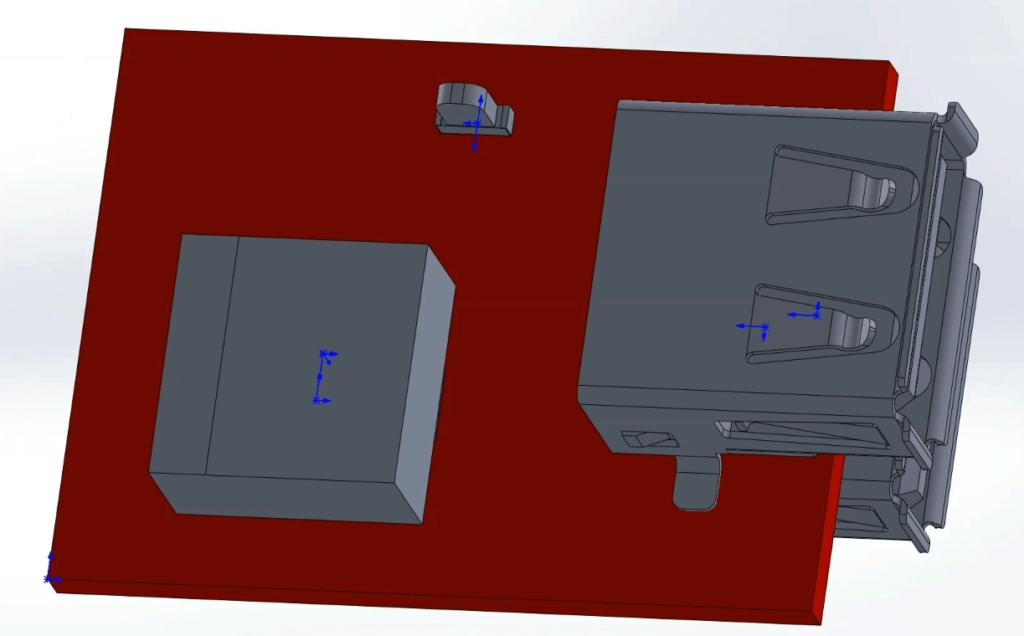
Step 65: View the imported result. All components placed in PCB Editor are placed in SOLIDWORKS.
Wrap Up & Next Steps
Quickly and efficiently collaborate between MCAD and ECAD teams and ensure an accurate final assembly with seamless bi-directional communication capabilities for SOLIDWORKS and Allegro X with MCADx. Upgrade to 23.1 to test out this and other new features in Allegro X.
