

SystemCapture
3D Visualization Support for System-Level Designs
A system-level design can be exported to a 3D system with a System Configuration File (.scf). When updating an existing 3D system, the export reflects the latest layout changes while preserving the existing 3D configuration.
This enhancement simplifies the transition from system-level design to 3D visualization for analysis and review.
MCM Board Support in System-Level Designs
MCM files can now be imported into system-level designs, in addition to board and module files. This enhancement extends pin-to-pin connectivity tracing and verification across MCM boards and other connected designs within the system.
Clarity 3D Quasi-Static Solver for Interconnect Model Extraction
The Interconnect Model Extraction workflow now supports the Clarity 3D Quasi-Static (QS) solver for RLGC model extraction. In addition to generating S-parameter models, designers can now generate RLGC models for simulation workflows and select the model type that best fits their analysis requirements.
Reflection Analysis with LayoutLink Profiles
The Reflection workflow now supports LayoutLink profiles, enabling reflection analysis of the interconnects defined across linked designs within a system configuration. This allows for easy analysis of any system configuration without manually recreating the system connectivity in the workflow.
Reliability Parameter Reuse
Validated reliability parameters can now be saved in reusable profiles, which can be applied to the same components across multiple designs.
Reliability data is maintained for each physical part and can be exported and imported to and from reusable profiles, enabling consistent application of approved reliability settings across designs. Support for CSV-based review and maintenance makes it easier to manage, update, and reuse reliability data.
Pulse Custom Variables
For projects managed in a Pulse environment, project archives now preserve the values of Pulse custom variables and are written to the project CPM file. Previously, custom variables defined in the Create New Project form were not retained when a project was archived and opened outside the Pulse environment. With this enhancement, project-specific information remains available when designs are shared with customers, partners, or other users who do not have access to the original Pulse environment.
Minimap for Schematic Navigation
The Properties panel now includes an overview subpanel called Minimap. It displays the entire schematic page in a zoom-to-fit view and highlights the area currently displayed in the workspace. When working in zoomed-in views, select a location in the minimap to quickly navigate to another area of the page.
Workspace Organization with Window Stacking
Windows and panels can now be stacked in a single container in addition to moving them to another monitor or workspace. This enables multiple windows and panels to be organized and accessed through tabs.
Enhanced Differential Pair Creation Capabilities
Automatic differential pair creation identifies matching positive and negative signals and groups them into differential pairs. In previous releases, this capability invoked a TCL command and relied on a configuration file. System Capture now uses the advanced differential pair creation capabilities available in Constraint Manager while retaining the existing menu command.
Pin Delay Import Validation
Pin delay values are commonly imported from external files during design creation and analysis workflows. Previously, the Import Pin Delay command imported data directly from a selected CSV file. The updated workflow adds automatic data detection, validation, and data review capabilities within the import dialog, allowing data to be reviewed and refined before it is applied to the design.
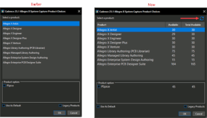 The Product Choices dialog now displays real-time license availability directly next to each license name. This allows users to view the number of available licenses before launching and select the one that is most appropriate, enabling informed selections and reducing launch failures. Additionally, a new Refresh License icon updates the license availability without relaunching the application.