Flow Planning
Location: PCB Layout (Allegro X)
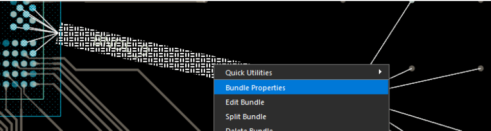
Allegro X AI will take any flow planning or bundling into account when completing routing on the PCB. This will help ensure accuracy of routing for critical buses and groups.
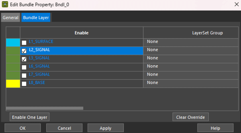
Allegro X AI follows the layer specified for each bundle for more granular control of layer assignment once on a bundle instead of individual nets.
Additionally, Allegro X AI follows the delay tuning settings in bundles for supported parameters. This gives designers the ability to assign delay tuning parameters for each pin pair for multi-pin nets through bundles and accelerates delay tuning assignment by specifying the assignment of delay tuning parameters once on the bundle instead of individual nets.
Layer Set DRCs
Location: PCB Canvas
Control layer-specific routing for high-speed interfaces and impedance-controlled nets by defining layer set design rule checks. Setup layer sets for nets requiring ‘layer pair’ based routing.
Configure Electrical Rules
Location: PCB Canvas
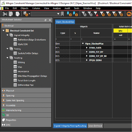
Electrical constraints can be used to improve the results of routing with X AI. The following constraints are supported by Allegro X AI and should be configured based on your design requirements:
- Min/Max Propagation Delay
- Relative Propagation Delay
- Total Etch Length
Advanced Routing Options
Location: Allegro X AI
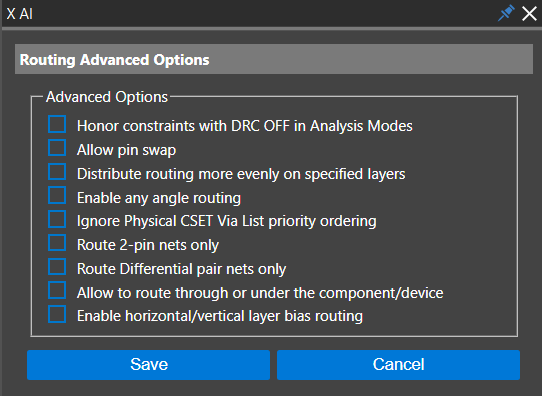
Advanced options can be configured to ensure the Allegro X AI router completes routing as desired. The following options are available for configuration:
Honor Constraints with DRC OFF in Analysis Modes
Allegro X AI will honor all constraints it currently supports, even if modes are off.
Need Help? Get instructions for configuring Analysis Modes here.
Allow Pin Swap
Swapping happens dynamically when routing. The log file will report the number of swap pins. For more information, run the Allegro Pin Swap Report.
Distribute Routing More Evenly on Specified Layers
By selecting this option, Allegro X AI attempts to balance distribution of routes over conductor layers.
Enable Any Angle Routing
By selecting this option, you give Allegro X AI permission to route the design using any angles necessary.
Ignore Physical CSet Via List Priority Ordering
By selecting this option, Allegro X AI will ignore priority within the via list and may leverage the smallest vias defined.
Need Help? Get step-by-step instructions on configuring the via list and other physical constraints here.
Route 2-pin Nets Only
By selecting this option, Allegro X AI will only route signal nets with 2 pins.
Allow To Route Through or Under the Component/Device
By selecting this option, you give Allegro X AI permission to route through or under devices and components on the PCB.
Delay and Phase Tuning
Location: Allegro X AI
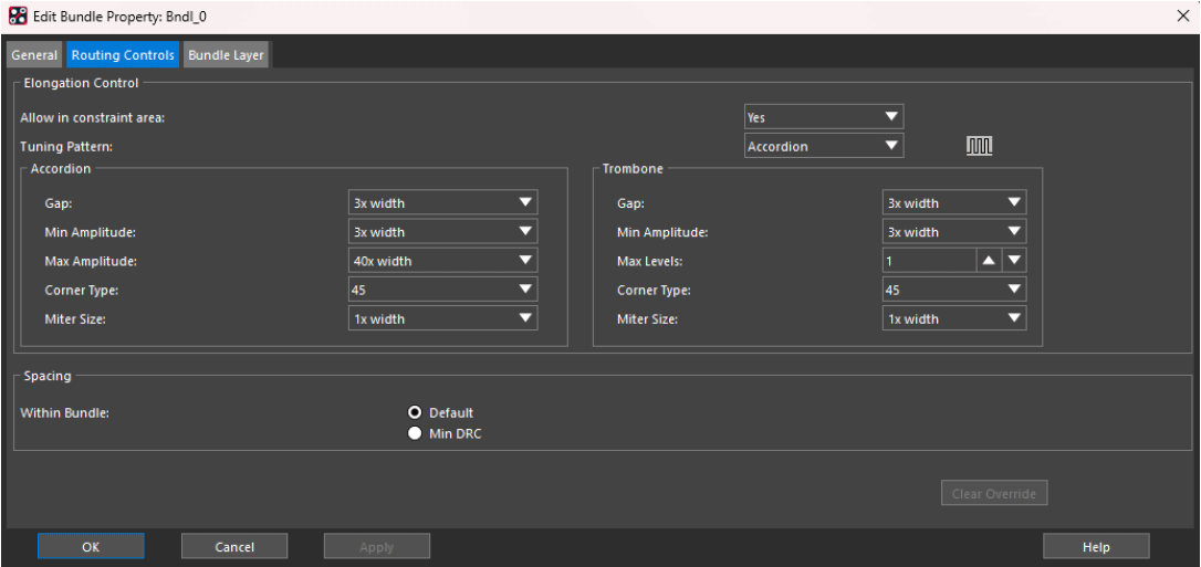
Configure the delay and phase tuning requirements for nets and differential pairs. Accordion and trombone patterns are supported for delay tuning. For phase tuning, a sawtooth pattern is supported. Parameters can be assigned using the pre-defined values located in the pull-down form for each parameter. This includes:
Accordion
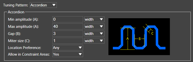
- Maximum Amplitude: Maximum allowable accordion tuning bump amplitude. Distance is measured from the base centerline to the top centerline of the accordion bump. The default value is 40x width.
- Gap: Minimum spacing between the legs of the accordion pattern. The default value is 3x Width.
- Miter Size: Size of the equal legs of an isosceles right triangle in which the hypotenuse forms the diagonal chamfer of the accordion bump.
- Location preference
- Allow in Constraint Area
Trombone
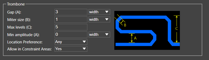
- Gap: Minimum spacing between the legs of the trombone pattern. The default value is 3x Width.
- Miter Size: Size of the equal legs of an isosceles right triangle in which the hypotenuse forms the diagonal chamfer of the trombone bump.
- Max Levels
- Minimum Amplitude
- Location Preferences
- Allow in Constraint Area
Sawtooth
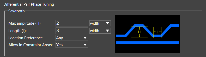
- Maximum Amplitude: Maximum allowable sawtooth tuning bump amplitude. Distance is measure from the base centerline to the top centerline of the sawtooth bump
- Length: Length of the top of the sawtooth bump measured between the segment vertices
- Location Preference
- Allow in Constraint Area
This will give the Allegro X AI router more guidance in meeting timing and/or length requirements for nets and differential pairs in the design.
