During the fabrication process, any variation in the position of the drill bit could sever a trace and open a net when through-holes are drilled. This possibility increases when incorporating thinner trace widths and smaller pad sizes to accommodate high-density boards. A fillet or teardrop, which is a triangular area of etch, can be added to reinforce connections and prevent signal failures; however, having to manually create fillets for every pin, via, or junction can be time-consuming. Automatically create fillets in OrCAD PCB Designer to prevent potential breakouts and errors due to drilling variations.
This how-to will provide step-by-step instructions on how to automatically add fillets to the PCB layout using the Glossing command in OrCAD PCB Designer Professional. To follow along, download the provided design above the table of contents.
How-To Video
Activating Gloss Parameters
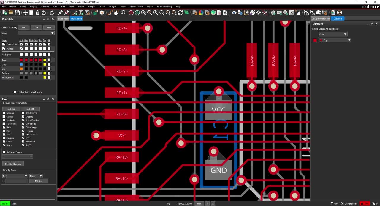
Step 1: Open the provided design, highspeed.brd,in OrCAD PCB Designer Professional.
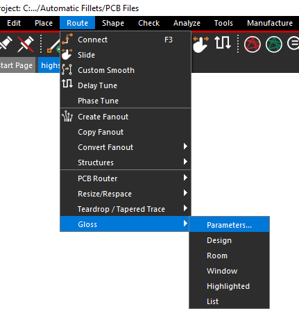
Step 2: Select Route > Gloss > Parameters from the menu.
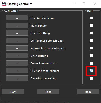
Step 3: Un-check all checked options under Run. Check Fillet and Tapered Trace.
Step 4: Select the Options button for Fillet and Tapered Trace to open the options window.
Configuring Fillet Options
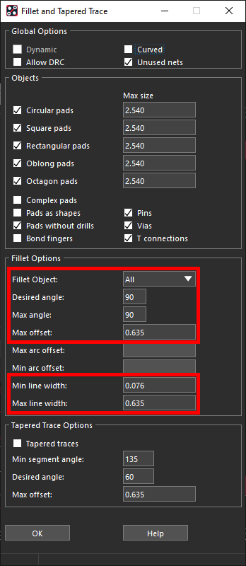
Step 5: Under Fillet Options, set the Fillet Object to All.
Note: Fillet Options define the objects in which fillets will be added. Select from All, Pins, Vias, and Ts. A T is an intersection of three or more lines. A fillet can be formed between any two of the lines in a T that intersect at an angle of 90 degrees or less and where the lines are drawn at an angle divisible by 45.
Step 6: Set the Desired Angle to 90.
Note: The Desired Angle specifies the angle created by the generated fillet shapes. A larger Desired Angle and a smaller Max Offset create a short fillet. A smaller Desired Angle and larger Max Offset create a long fillet.
Step 7: Set the Max Angle to 90.
Note: The Max Angle specifies the maximum angle for the fillet. The maximum possible value is 99. This value must always be equal to or greater than the Desired Angle.
Step 8: Set the Max Offset to 0.635.
Note: The Max Offset specifies the maximum distance between the intersection of the pad edge and the connecting line, forming the fillet length. If the design units are in mils, set this value to 25 mils.
Step 9: Set the Min Line Width to 0.076.
Note: The Min line width specifies the minimum line width of the cline entering the pad. If the line width of the cline is less than the value specified here, the fillet is not created. Minimum line width should be set to the minimum capabilities of your manufacturer. If designing in mils, set this value to 3.
Step 10: Set the Max Line Width to 0.635.
Note: The Max Line Width specifies the maximum line width of the cline entering the pad. If the line width of the cline is greater than the value specified here, the fillet is not created. If designing in mils, set the maximum line width to 25 mils. Typically, anything over 25 mils will not be affected by drill offset.
Step 11: Click OK to save the settings.
Automatically Adding Fillets
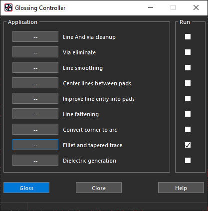
Step 12: Select Gloss in the Glossing Controller window to start the glossing.
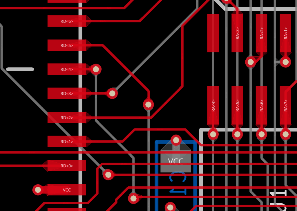
Step 13: Zoom in on a set of pads or mounting holes. The fillets have been added to the traces.
Wrap Up & Next Steps
Quickly and efficiently create fillets or teardrops to prevent any errors due to variations in drilling with the automatic fillet feature in OrCAD PCB Designer. Test out this feature and more with a free trial of OrCAD.

