
Configuring Individual Shape Parameters
Step 1: Open the provided design in OrCAD X Presto.
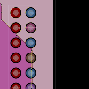
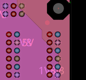
Step 2: Click to select the rightmost 3.3V plane on the PWRB layer. Several through pins on this plane failed to connect due to insufficient area. The Properties panel populates with properties for this shape.
Step 3: In the Properties panel, scroll down to the Thermal Reliefs section. Select TH to view the through-pin thermal relief settings.
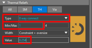
Step 4: Select 8-Way Connect from the Type dropdown. This will allow more spokes to connect to through pins if necessary. Enter 1 for the minimum number of connections.
Step 5: Set the Width to Constraint + Oversize and enter 0.254 for the value. This will increase the width of each thermal relief by 0.254mm.
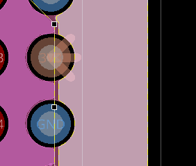
Step 6: View the thermal reliefs in the PCB canvas. Previously unconnected pins are now connected to the plane with wider thermal reliefs.
Configuring Global Shape Parameters
To configure these thermal relief and shape parameters throughout the whole design instead of just on the 3.3V plane, parameters can be configured globally.
Step 7: To do this, select Setup > Design Parameters Editor from the menu.
Step 8: In the design settings window, select Shapes from the list on the left.
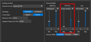
Step 9: Under Thermal Reliefs, select 8 Way Connect from the THT Pins dropdown. Set the minimum count to 1 and the maximum count to 4.
Step 10: Set the Thermal Width to +Oversize. Enter 0.254 into the text field.
Step 11: Click Update All Shapes and close the Design Settings window.
Step 12: View the pins connected to power and ground planes. All thermal reliefs are wider, and diagonal reliefs are incorporated where required.
Configuring Shape Parameters
Step 1: Open the provided design in OrCAD X PCB Editor.
Step 2: Select Setup > Design Parameters from the menu.
Step 3: In the Design Parameter Editor window, select the Shapes tab.
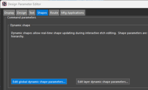
Step 4: In the Shapes tab, select Edit Global Dynamic Shape Parameters to configure the parameters.
Step 5: The Global Dynamic Shape Parameters window opens. Select the Thermal Relief Contacts tab.
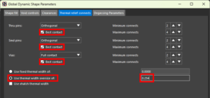
Step 6: Check the options for Best Contact for Thru Pins, SMD Pins, and Vias. Selecting Best Contact will allow OrCAD X to automatically adjust the thermal relief pattern to make the best contact. For example, if the thermal relief setting is set to orthogonal but one of the pin pads has no good way to establish an orthogonal connection, “best contact” allows it to connect diagonally instead.
Step 7: Select User Thermal Width Oversize Of and enter 0.254 into the text field. Click OK.
Step 8: Click OK in the Design Parameter Editor window to save the settings and close it.
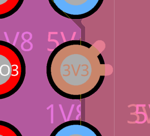
Step 9: View the 3.3V pin. Two wider thermal reliefs have been added to connect the pin to the 3.3V net.

