During the PCB layout process, components will often have to be moved to optimize space, shorten connections, and improve the layout. If routing has already occurred, the change may not only need to be made to the component itself, but any traces and surrounding components connected to it as well. A variety of new features can help designers efficiently move components in OrCAD X Presto, including:
- Etch ripup
- Etch slide
- Absolute location
- Relative locations
- Alignment guides
- Defining x and y coordinates
This quick how-to will provide step-by-step instructions on how to efficiently move components in OrCAD X Presto Professional.
To follow along, download the provided files above the table of contents.
How-To Video
 Open in New Window
Move Components in OrCAD X Presto with Etch Slide
Step 1: Open the provided design in OrCAD X Presto Professional.

Step 2: This design has 3D DRC errors that can be corrected by moving the connectors. Select the Move mode from the toolbar.
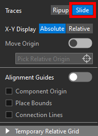
Step 3: The Move widget opens to show the options available for moving a component. Select Slide for Traces to move a connected component and slide its traces.
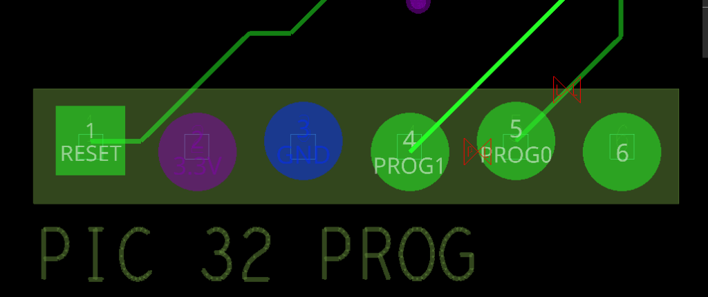
Step 4: Select connector JP2 at the bottom of the board from its leftmost pin to attach it to your cursor.
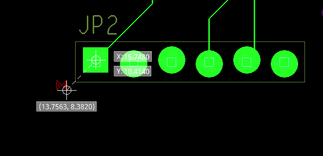
Step 5: Move your cursor around. The connector moves with your cursor and its traces are adjusted to keep it routed.
Note: Two sets of coordinates are shown while the component is being moved. One set shows the original position of the component at the point at which it was selected. The other shows the position the component will be placed at with the cursor in its current location.
Move Components in OrCAD X Presto with Alignment Guides
Step 6: In the Move widget, enable the option for Alignment Guides. A magenta outline appears around the component.
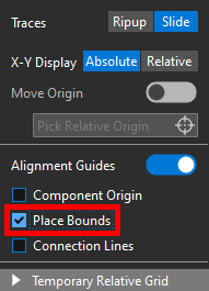
Step 7: Check the option for Place Bounds to align the component by other the placement boundaries of other components on the board.
Note: Other alignment options available include:
- Component Origin: Align the component on the X or Y origin axes of any other component on the board.
- Connection Lines: Align the selected pin to an existing connect line.
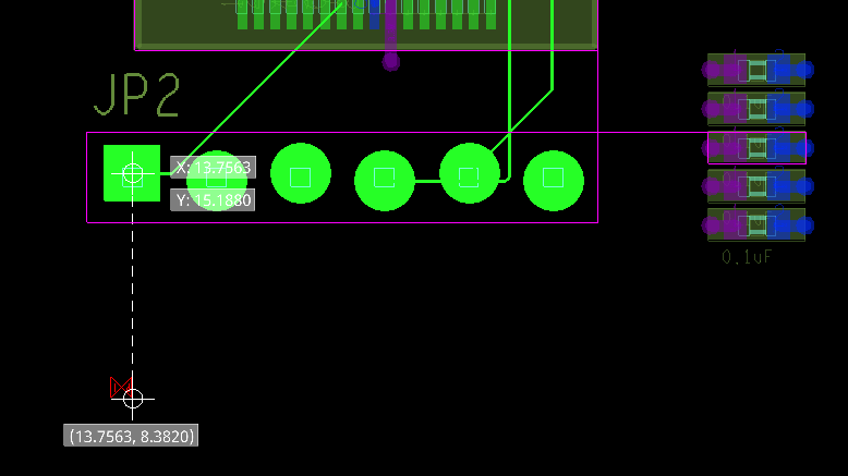
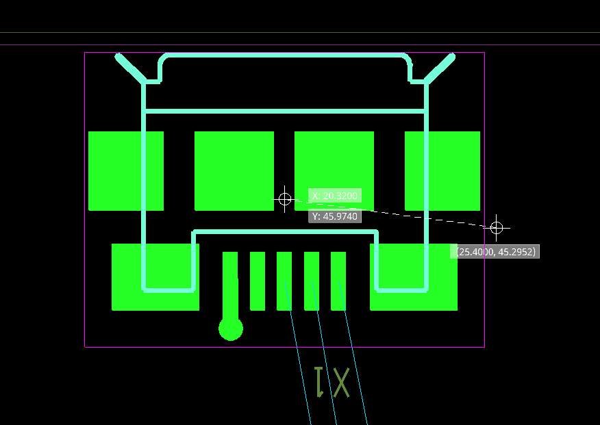
Step 8: Move the cursor to align the connector with the right edge of IC1 and the top edge of the middle capacitor in the array to the right as shown above. Click to place the connector.
Note: The traces now intersect with the pads on the connector and IC1, creating a shorting DRC error. This will be corrected in the following steps.
Step 9: Select the Slide mode from the toolbar.
Step 10: Click to adjust the traces between JP2 and IC1 to clear the shorting DRCs. Click to select a trace and click again to place it.
Move Components in OrCAD X Presto with Etch Ripup
Note: If a component has critical traces, such as differential pairs, or is being moved to a completely different position on the board, the ripup mode can be used to remove all traces.
Step 11: Select the Move mode from the toolbar.
Step 12: Select Ripup for traces in the Move widget to delete any traces connected to the moved component.
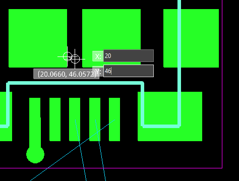
Step 13: Select the center of USB connector X1 to attach it to your cursor. Move the connector until its new X and Y coordinates read approximately 20 and 46, respectively, and click to place.
Note: All connections between X1 and IC1 are removed. With the component in the correct location, these traces will need to be routed again. The connection to GND, however, remains on the connector, as it is a via fanout, not a full trace.
Move Components in OrCAD X Presto to an Absolute Location
Note: A component can be placed with even more precision by entering the desired location. In the absolute X-Y display mode, the coordinates shown when moving a component are absolute with respect to the design origin.
Step 14: Select X1 again to attach it to your cursor.
Step 15: Press Tab on the keyboard to edit the coordinate text fields.
Step 16: Enter 20 for the X coordinate and 46 for the Y coordinate. The connector is placed and detached automatically.
Step 17: It is recommended that all components with strict location requirements, such as connectors, be locked as soon as they are placed. Select the Lock button in the Properties panel to lock the connector in place. Click anywhere in the canvas to deselect the connector.
Move Components in OrCAD X Presto with Relative Coordinates
Note: The relative display mode can be used to show coordinates with respect to the original position of the component or a selected location.
Step 18: Select the Move mode from the toolbar.
Step 19: Select the Slide mode for Traces in the Move widget.
Step 20: Select Relative for the X-Y Display and enable the option for Move Origin.
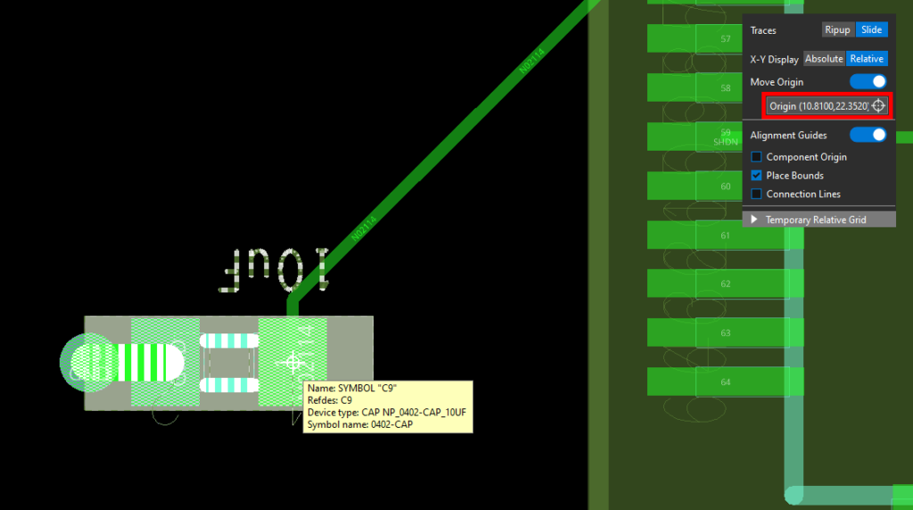
Step 21: Select Pick Relative Origin and click the right pin of capacitor C9. The origin is shown in the Move widget.
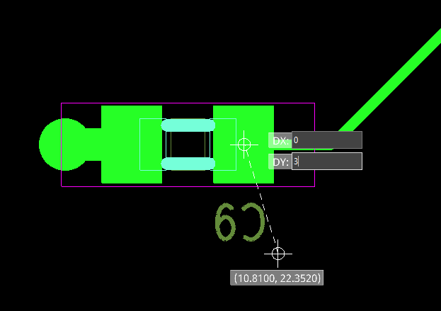
Step 22: Select the capacitor to attach it to your cursor. Press Tab and enter 0 for DX and 3 for DY. Press Enter to move the capacitor.
Step 23: The capacitor is moved and the connection to IC1 remains intact. Choose the Select mode from the toolbar to finish the Move mode.
Wrap Up & Next Steps
Quickly and efficiently move components in OrCAD X Presto with a variety of new features to expedite your PCB layout. Test out this feature and more with a free trial of OrCAD X. For more how-tos and step-by-step walk-throughs, visit EMA Academy.

