With design form factors becoming smaller and more complex, creating an accurate board outline early in the design process is essential. While dimensions and drawings provided by the mechanical engineering team can be used to approximately determine edge and hole locations, it is much easier and less error-prone to create a board outline directly from the CAD file. An Incremental Design Exchange (IDX) file can be used to efficiently transfer information between ECAD and MCAD design teams for both baseline data and updates. Easily import a board outline from an IDX file with OrCAD X Presto. With OrCAD X Presto, easily create a board outline from mechanical files including:
- DXF
- IDF
This quick how-to will provide step-by-step instructions on how to import a board outline from an IDX file in OrCAD X Presto.
To follow along, download the provided files above the table of contents.
How-To Video
 Open in New Window
Creating a Board File
Step 1: Open OrCAD X Presto.
Step 2: Select File > New > Board from the menu. This will automatically create a board file in your home directory.
Step 3: Select File > Save As from the menu.
Step 4: Browse to the working directory. Enter IDX_Board for the board name and click Save.
Import a Board Outline from an IDX File
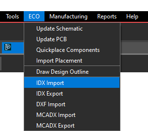
Step 5: Select ECO > IDX Import from the menu.
Step 6: The IDX In window opens. Select the ellipsis to browse for the model file.
Step 7: Select the provided Special_Outline.idx file and click Open.
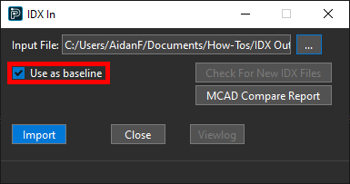
Step 8: Ensure Use as Baseline is checked and click Import to start the import. The Use as Baseline option specifies the IDX data as a base design for future iterations.
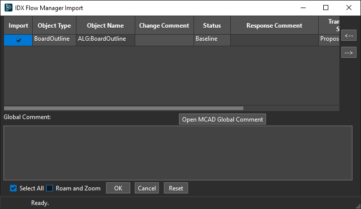
Step 9: The IDX Flow Manager Import window opens. Check the option for Import for the BoardOutline object to import the board outline.
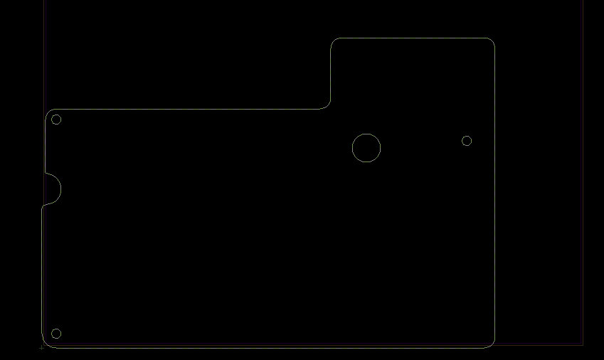
Note: A preview of the board outline appears in the PCB canvas.
Step 10: Click OK. The outline is imported and replaces the existing board outline.
Step 11: Click Close to close the IDX In window.
Creating Keepin Geometry
Note: IDX files may or may not include keepin geometry. When you import a board outline from an IDX file, keepin geometry is added automatically. If the IDX file includes keepin geometry, this will be automatically mapped in OrCAD X Presto. When the design outline was imported, the package and route keepins retained the shape of the original outline. This will be corrected in the following steps.
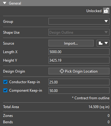
Step 12: Select the imported outline. The Properties panel is populated with its properties.
Step 13: Uncheck the options for Conductor Keep-in and Component Keep-in.
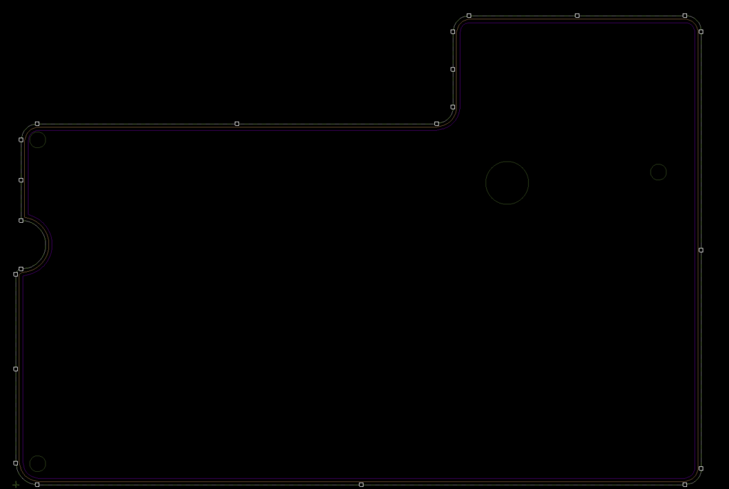
Step 14: Recheck the options to generate keepins for the new outline. New keepins that follow the irregular shape of the outline are added.
Wrap Up & Next Steps
Quickly import a board outline from an IDX file to accurately define the size, shape, and features of the PCB with OrCAD X Presto. Test this feature and more with a free trial of OrCAD X. Get more how-tos for OrCAD at EMA Academy.

